This section illustrates the configurations that are common across most of the adapters. However, if there are any additional component-specific details which are not described here, such details can be found in the respective component help file.
Customization to the configuration can be done through Configuration Property Sheet (CPS) and Properties panel; CPS having Component-specific configuration and Properties having Component Instance configuration.
Properties Panel
To view/edit properties, use any one of the two options below in the Orchestrator:
- Right-click the component present in the Fiorano Orchestrator and click Properties.
- Open from Window > Show View > Other > General > Properties
Properties section has subsections where Component Instance values can be edited based on the requirement, such as General, Deployment, Execution, Log Manager, Log Module Instances, and Runtime Arguments.
Component Instance Properties
Component instance properties appear in the Properties pane when a component present in the Fiorano Orchestrator is selected. These properties and the attributes present under it are explained in the sections below.
General
This group contains general properties that identify the component instance or affect the appearance of the component instance.
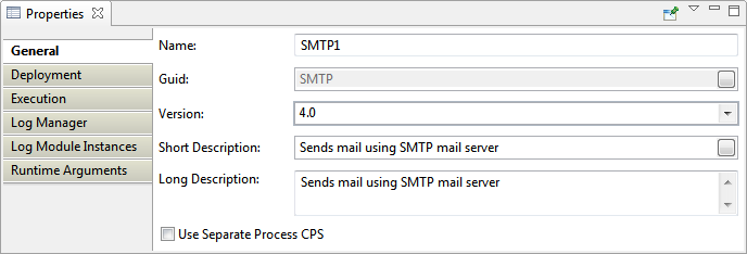
Figure 1: General properties for a sample component
Name
Name of the component instance in the application. This name should be unique in an application.
Guid
Guid (Global Unique Identifier) is a unique name used as an identifier to represent a service/component. This is generally the name of the component itself.
Version
When there are multiple versions of a component with the same GUID, the Version property determines the component that this instance represents.
Example: Web Service Consumer has two versions of components, version 4.0 and version 5.0. Version 4.0 uses axis API and version 5.0 uses axis2 API.
Short Description
A one line description for the component instance. This description is shown as a tooltip for the component. By default, the value defined for short-description element in the component's Service Descriptor is shown here. If there is no value defined for this property, the default value is shown in tooltip.
Example: For an SMTP component that is configured to send emails using a Fiorano email account, the short description can be amended to give a more appropriate description.
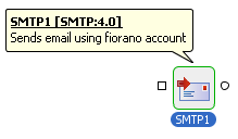
Figure 2: Tooltip showing the changed Short description for SMTP component
Long Description
A detailed description about the component instance. By default, the value defined for long-description element in the component's Service Descriptor is shown here.
Use Separate Process CPS
Select this check box to use external Configuration Property Sheet (CPS) on a separate JVM instead of the interface available in eStudio. When you open the CPS from the Fiorano Orchestrator after selecting this option, the external CPS opens up. This option can be used when loading the default eStudio CPS is complex and takes up too much memory.
Deployment
It contains the deployment information of the component, which affect the way components are deployed in Fiorano environment. The Peer Server node on which the component has to be launched, and the can be configured here.
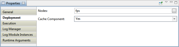
Figure 3: Deployment properties in the Properties panel
Nodes
A delimited list of Peer Servers from Fiorano network on which this component instance is launched. The component is launched on the first Peer Server in the list that is available in Fiorano network. If the Peer Server on which the component instance is running shuts down, the component instance fails over to the next available Peer Server.
Click the button against Nodes option to launch Select Nodes editor to configure the Peer Servers.

Figure 4: Editor to configure Peer Servers on which the component instance can launch
The peer server present in the Fiorano network appears under Selected Nodes section in the Select Nodes editor. This can be moved to Available Nodes section and used accordingly as mentioned below:
- To add a Peer Server - Select the server you need to add from the Selected Nodes section and click the
 button. The selected server gets added to Available Nodes section.
 - To remove a Peer Server - Select the Server you need to remove from the Available Nodes section and click the
 button. The selected server gets added back to Selected Nodes section, which means this server will not be available for the Service Instance anymore.
 To add/remove multiple servers - Use
 and
and  to move all the Selected Nodes to Available Nodes and all the Available Nodes to Selected Nodes respectively.
- To change the order of the Peer Servers - Order of priority can be changed using the Up button and the Down button in case of multiple servers.
Based on the selected Peer Server, the component color changes to give a visual clue as to which Peer the component is configured to launch. By default, when a Peer Server is added to an Enterprise Server, a unique color is chosen. In the below figure, the Feeder and Display components are configured to launch on different servers.
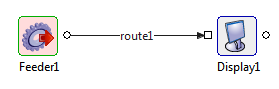
Figure 5: Change in component color representing different peer servers attached
Cache Component
During the development process, some components might have external resources added. Also, for custom-built components, the source files might be updated from time to time. To reflect the changes for such components across the peers at runtime, enable this property to force the resources of the component to be re-fetched each time a Connectivity and Resource Check is done.
- yes
Resources required for execution by the component instance are fetched from the Enterprise Server and cached on the Peer Server (if not already done) when the CRC (Check Resources & Connectivity) operation is performed in the Event Process.
A resource can be marked as required for execution in the Service Descriptor.
If the resources are not changed in the Enterprise Server, then they need not be fetched every time the application is launched, thereby reducing the time taken to perform a CRC operation for the application.
no
The resources required for execution by the component instance are fetched from the Enterprise Server to the Peer Server every time the CRC operation is performed.
Execution
This group contains properties that affect launch behavior of the component.
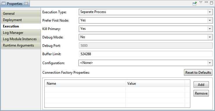
Figure 6: Execution properties in the Properties panel
Execution Type
This property specifies how the component instance is launched. There are four possible values.
- Separate Process: The component instance is launched in a separate JVM. It is automatically launched when the application is launched. When this option is selected properties Debug Mode and JVM_PARAMS are visible.
- In Memory: The component instance is launched in the JVM of the Peer Server. It is automatically launched when the application is launched. When this option is selected properties Debug Mode and JVM_PARAMS are not visible.
Group Process: This launch mode enables multiple microservices to run in a Single JVM sharing the same resources. This launch mode overcomes certain limitations faced by the two modes mentioned above - the Separate launch mode having a restriction to use a limited number of microservices in a peer and the In Memory launch mode affecting the peer server performance when microservices face memory/thread leak.
Manual: The component instance is not launched when the application is launched. It has to be launched manually from the command line.
- None: If selected, the component instance is never launched. When this option is selected properties Debug Mode is not visible and the value for property JVM_PARAMS is ignored.
The boundary of the component icon is changed to provide a visual clue for the launch type selected. The below figure shows the change in the boundary of a component instance for each launch type.![]()
Figure 7: Boundary of component instance providing visual clue for launch type
Prefer First Node
To prefer the first launch on the highest available node, that is, whether or not the launch of this service instance is preferred on the highest level.
Kill Primary
To kill Primary Service Instance when Secondary launches.
If a service is bound to a Peer Server and when another service with the same name tries to bind with the same Peer Server, then the 2 options available are:
- Yes
Primary service will be killed and secondary service will take its place. - No
Secondary server kills itself.
Debug Mode
- yes
The component instance is launched in debug mode. A debugger from any IDE can be attached to the component instance to debug the component instance step by step at runtime. When this value is selected, the property Debug Port is visible.
- no
The component instance is not launched in debug mode and a debugger cannot be attached. When this value is selected, the property Debug Port is visible.
This property is only used when the property Launch Type is set to Separate Process. To debug the component instance launched in the memory of Peer Server JVM, debug parameters have to be in the configuration file – %FIORANO_HOME%\esb\fps\bin\fps.conf – of the Peer Server.
Debug Port
The port on which the component waits for instructions from the debugger.
When property Debug Mode is set to yes, then the property Debug Port is set to 5000. It is equivalent to launching the component with the following command line arguments: -Xdebug -Xrunjdwp:transport=dt_socket,server=y,suspend=n,address=5000
Buffer Limit
Maximum buffer size (bytes) that to be stored per port. The Peer Server starts generating alerts when the number of bytes comes close to this limit.
Configuration
The serialized configuration of the component instance. Any changes made to this are reflected when the component instance is launched or the CPS of the component instance is opened.
Connection Factory Properties
Connection Factory settings modified from peer connections will be lost when the component is stopped or event process is stopped. In order to make it persistent, add connection factories which thereby gets added in EventProcess.xml file for the specified Service Instance.
Click Add button and select the property from the Name drop-down and provide appropriate value to save a particular Connection Factory property.
Log Manager
Contains logging information as described below.
- Type: Type of log handler, for example, File, Console.
- Class Name: Class name of the specific Log Type.
- Directory: Name of the directory where Log files are stored.
- File Size: The maximum file size after which a new Log file has to be created.
- # of files: Maximum number of Log files to be maintained.
- Include Time Stamp: To include Time-stamp in Log Message
- Time Stamp Format: To set the format in which time stamp needs to appear in the Logs. Default value is "MM/dd/yyyy HH:mm:ss"
Log Module Instances
This group contains different loggers that are used and their log level configuration.
All the loggers that are used by the component instance are shown as properties in this section. The level at which logging should be performed for each logger is defined below.
There are nine logging levels (Values) available in the drop-down list – Off, Severe, Warning, Config, Info, Fine, Finer, Finest, and All.
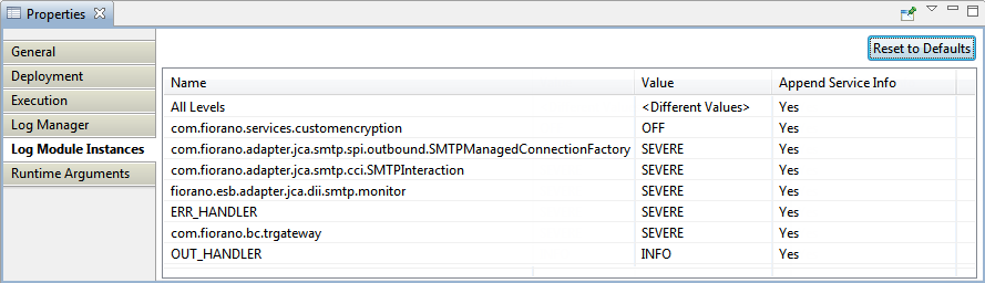
Figure 8: Log Module Instances properties in the Properties panel
When the component is launched, all the component log module instance names are modified to include Event Process name, Service Instance name and Service GUID to maintain uniqueness.
For example, if the log module instance name of a component is "com.fiorano.services.display.DisplayService", then after the component is launched, some extra information is included and is changed to "EVENT_PROCESS1.COM.FIORANO.SERVICES.DISPLAY.DISPLAY1.DISPLAYSERVICE" and the logger is created with the changed name. In the above example, the log module instance name has the service GUID name "Display".
If the original name doesn't have Service GUID name, then Application Name, Sevice GUID, and Service Instance name is pre-pended to the log module name. For example, if the log module instance name is "org.apache.ws.security.processor.SignatureProcessor", then after the component is launched, it is changed to "COMMUNICATIONS_IN.WSSECURITY.WSSECURITY1.ORG.APACHE.WS.SECURITY.PROCESSOR.SIGNATUREPROCESSOR" and the logger is created.
Changing the log module instance names at component startup is required to maintain the uniqueness of components logs especially when multiple instances of a component are running in the same JVM.
However, this does make logging from 3rd party jars difficult to manage when working with custom components. To avoid this, the property Append service Info is useful for controlling log levels of loggers used by third-party libraries, since the handlers for such loggers will be created without appending service info to the logger names used by them.
For information about log levels and the effect they have on logs generated, please refer to http://java.sun.com/j2se/1.4.2/docs/api/java/util/logging/Level.html.
Runtime Arguments
Contains the information about the runtime arguments for the service. It has a single property JVM_PARAMS which contains all command line parameters that are passed to launch the component.
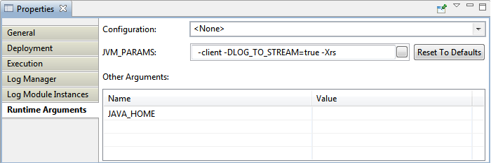
Figure 9: Execution properties in the Properties panel
This property is used only when the Launch Type of the component instance is set to 'Separate Process'. Any system properties can be set using this property.
JVM_PARAMS section contains the JVM parameters that are used while launching the component. Whenever a change is made in JVM PARAMS section, the Update all Service Instances dialog box appears asking whether the change has to be updated for all the service instances in all Event Process having the same JVM PARAMS value.
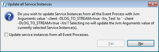
Figure 10: Dialog box prompting to update all Service Instances or to update only the present instance
If No option is selected, then it updates to the current service instance. If Yes option is selected, a dialog listing the service instances with same JVM PARAMS value appears and the required service instances can be selected for an update.
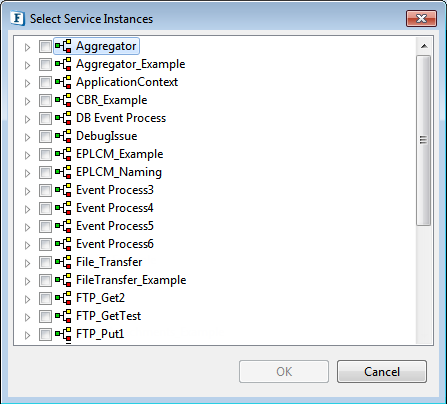
Figure 11: Select Service Instances
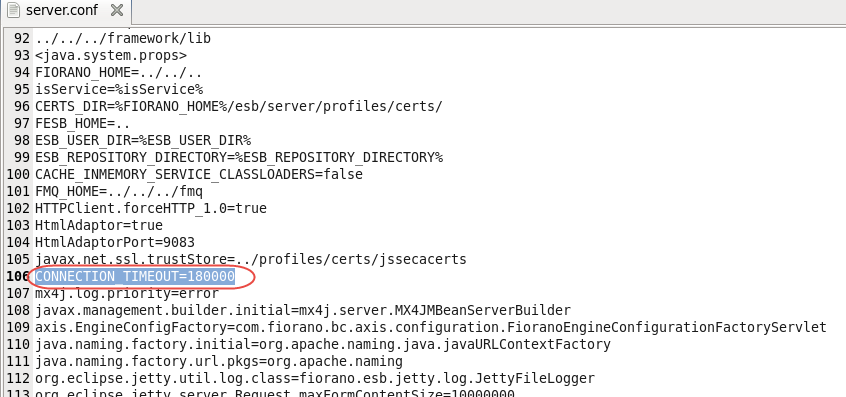
Configuring Connection Timeout
In microservices such as FTPGet, FTPPut, and FileReader, an input/output operation may get hung for indefinite time waiting for a request to return due to various reasons such as network fluctuations of the mounted directory. To avoid such waiting time, it is recommended to configure Connection Timeout in the runtime arguments. This is done by adding a property "-DCONNECTION_TIMEOUT" with the value (in milliseconds) as per requirement in Runtime Arguments in the Properties pane.
To configure Connection Timeout,
- Click the microservice present on the orchestrator editor.
In the Properties pane, click the Runtime Arguments tab and append the following values in the JVM_PARAMS text area:
Append to the JVM_PARAMS values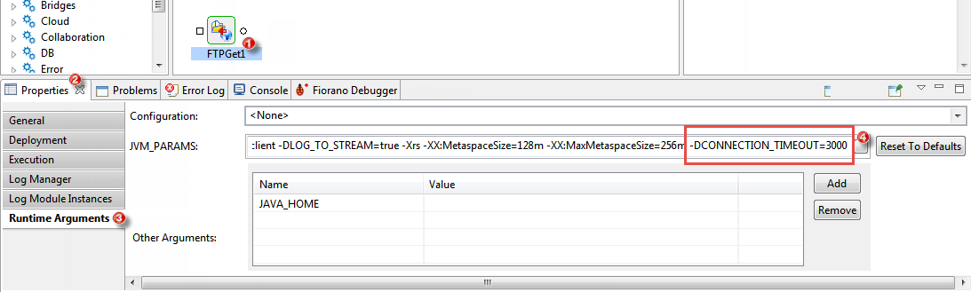
Figure 12: Configuring the runtime arguments by editing the JVM_PARAMS value to manage memory- Press Enter to save the configuration and click the option "No" or "Yes" to update this configuration only to the current service instance alone or for all event process respectively.
Port Properties
Component port properties can be configured by choosing the port and configuring the appropriate property in the Properties panel.
Input Port Properties
Input port properties appear in the Properties pane when the input port of a component instance is selected.
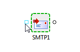
Figure 14: Input Port properties selected/highlighted
Input port properties for an SMTP component are explained below.
General
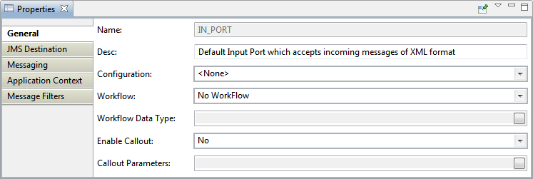
Figure 15: Input port General properties for a sample component instance
Name
Name of the Input Port
Desc
Description to brief the functionality of the port.
Configuration
The serialized configuration of the component instance. Any changes made to this are reflected when the component instance is launched or the CPS of the component instance is opened
Workflow
Specifies the role of this port in the workflow. The options available are:
- No WorkFlow
- Workflow Item
- Workflow End
Workflow Item and Workflow End can be selected accordingly to specify the role of the port. When either of these ports is selected, the next attribute 'Workflow Data Type' gets highlighted for further customization.
Workflow Data Type
This attribute is used to specify the part of the document that needs to be tracked, which helps Document Tracking. The attributes that can be tracked are:
- Message Header
- Message Body
- Attachments
- Application Context
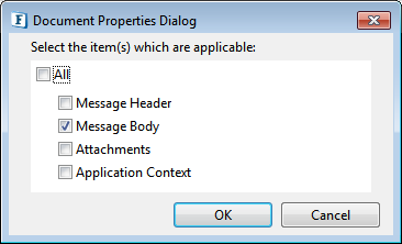
Figure 16: Dialog box to choose Work Data Type
Please refer to Document Tracking for more information.
Enable Callout
Specifies whether the Callout config is enabled or not.
Callout Parameters
Specifies DB callout parameter types for the workflow.
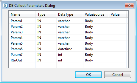
Figure 17: Execution properties under Property panel
JMS Destination
This group contains properties related to destinations created for the ports of the component.
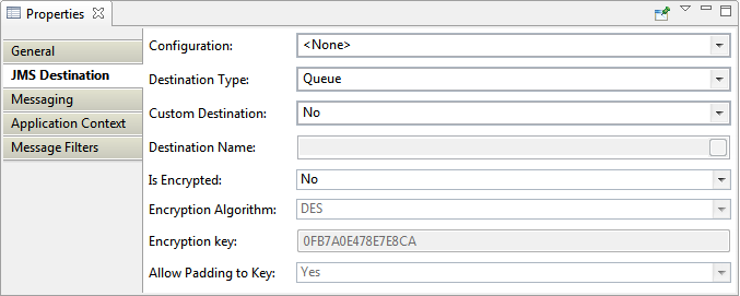
Figure 18: Execution properties in the Input Port Properties panel
Configuration
The serialized configuration of the component instance. Any changes made to this are reflected when the component instance is launched or the CPS of the component instance is opened.
Destination Type
Specifies whether the destination for the port is 'Queue' or 'Topic'. Visual representation of port is changed based on the type of the destination as shown below. Square shape indicates a Queue and a circle indicates a Topic.
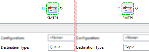
Figure 19: Input port as queue and as topic
- When this property is set to Queue, the property Durable Subscription is not visible.
- When this property is set to Topic, the property Durable Subscription is visible.
Custom Destination
Destinations for each port in the application are created automatically and associated with a port when the application is launched. The destination name for destination created and associated to a port is constructed using the following function:
<Event Process GUID>_<Component instance name>_<Port name>
Example: If an Event Process whose GUID is SAMPLE_APP contains an SMTP component instance with name MAIL_SENDER. The destination created for the input port is SAMPLE_APP_MAIL_SENDER_IN_PORT.
However, if the destination to be used has to be explicitly defined, then this property should be set to yes.
- When this property is set to yes, the property Destination Name is visible.
- When this property is set to no, the property Destination Name is not visible.
Destination Name
The name of topic or queue that has to be associated with the port. The destination is automatically created if it is not present.
Destination Encryption
Destination Encryption allows storage of sensitive data from different publishers in a secure way. Encryption implies the transformation of plain text into cipher text by using "key" A key is also used to decrypt the cipher text into plain text.
Destination Encryption Characteristics
In Destination Encryption, all messages sent to a particular destination (topic or queue) are encrypted, thus providing a secure channel of delivery. A component does not have to encrypt the message explicitly like in Message Encryption. A destination is marked as encrypted at the time of its creation. All messages published on this destination are encrypted before storing those in the database and delivered decrypted to subscribing applications. A client application, therefore, does not have to explicitly decrypt a received message.
Base Implementation
Fiorano 9.5.0 and higher versions support Destination Encryption.
DES (Data Encryption Standards) is used as the default encryption algorithm. In addition to that Fiorano 11 supports Base64, TripleDES, AES256, AES128, AES192, RC2-40, RC2-64, and RC2-128.
The Destination Encryption function uses the library cryptix.jar provided by Cryptix for generating keys as well as for encryption. This file comes bundled with the Fiorano 11 installation. It can be found in the FIORANO_HOME/extlib/cryptix directory of the Fiorano 11 installation.
Destination Encryption involves only encrypting the payload of the message and not its JMS headers and properties.
Encrypted Destination Creation
Input/Output port properties appear in the Properties panel when an input port of a component instance is selected.
Is Encrypted
- Yes
Encrypted JMS destination will be created. - No
Non Encrypted JMS destination will be created.
Encryption Algorithm
The supported algorithms are DES, Base64, TripleDES, AES256, AES128, AES192, RC2-40, RC2-64, and RC2-128.
Encryption Key
Specify key which is used to encrypt the incoming data. Specify 64 digit key for AES256, 48 digit key for AES192, 32 digit key for AES128, 16 digit key for DES, 48 digit key for TripleDES, 10 digit key for RC2_40, 16 digit key for RC2_64 and 32 digit key for RC2_128.
Allow Padding to Key
Choose yes to allow padding to the key to match the value required for the mentioned algorithm.
Messaging
This group contains properties related to JMS messaging concepts. In general, pre-built components provided by Fiorano use a single connection and share the same session for reading messages in the input port and sending messages to the output port.
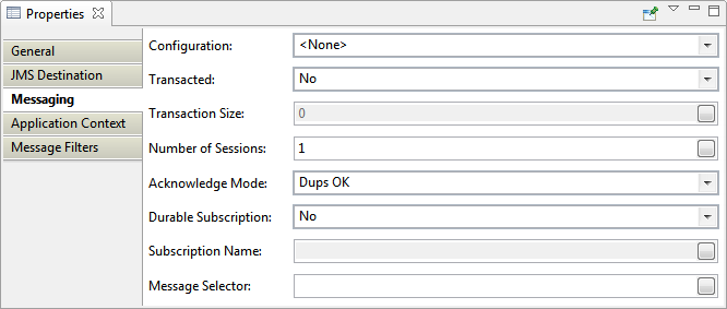
Figure 20: Messaging properties in the Input Port Properties panel
Configuration
The serialized configuration of the component instance. Any changes made to this are reflected when the component instance is launched or the CPS of the component instance is opened.
Transacted
Specifies whether the JMS session is transacted or not.
- yes - JMS session is created as a transacted session. Multiple input messages can be grouped into a single transaction. Messages are not sent on the output port of the component until the transaction is complete. They are held in-memory of the component. When this value is selected, property Transaction Size is visible.
- no - JMS session is created as a non-transacted session. Messages are sent on the output port of the component immediately. When this value is selected, property Transaction Size is visible.
A transaction is based on the number of input messages processed and not based on the number of output messages sent. In cases, where a component sends a large number of output messages for each input request, it is not advised to set this property value to yes even if the value for property Transaction Size is set to 1.
Example: A File Reader component reading a large binary file or a DB component that returns a result set containing a large number of rows.
Transaction Size
Number of input messages that should be processed before committing the transaction.
Number of Sessions
Number of sessions that are created by the component instance to process messages received on the input port. Messages are processed in a separate session by each thread. This property is used to increase the number of threads that can process the requests and thereby increase the throughput. However, the number of threads that can at a time is restricted by Max Pool Size property in Connection Pooling Configuration panel.
Acknowledgement Mode
Specifies the acknowledgment mode that is used to acknowledge messages. Messages are not deleted from destinations until they are acknowledged. When the component fails over because of the HA failover of Peer Server, all the messages that are not acknowledged are redelivered. The number of duplicate messages in case of failover can be controlled using this property.
DUPS OK
Messages are acknowledged after configured number of messages are successfully processed and output messages are sent by the component instance. The number of messages after which the messages are acknowledged can be configured at the following node in FMQ profile – Fiorano > mq > pubsub > TopicSubSystem > DupsOkBatchSize. Number of duplicate messages is utmost the DupsOkBatchSize for each session on each input port of the component instance.
AUTO ACKNOWLEDGE
Messages are acknowledged after a message is successfully processed and the output message is sent by the component instance. Hence, number of duplicate messages is utmost 1 for each session on each input port of the component instance.
CLIENT ACKNOWLEDGE
This property is ignored if the property Transacted is set to yes. When the property Transacted is set to yes, messages are acknowledged when the transaction is committed. Hence, number of duplicate messages is utmost the number denoted by property Transaction Size for each session on each input port of the component instance.
Durable Subscription
Specifies whether a durable subscriber is created on the destination represented by the input port or not. This property is visible only when the value for the property Destination Type is set to Topic.
- yes - A durable subscription is created to the topic represented by the input port. Messages sent to the topic are not lost when the component fails over because of the HA failover of Peer Server. If selected, then the property Subscription Name is visible.
- no - A durable subscription is created to the topic represented by the input port. Messages sent to the topic may be lost when the component fails over because of the HA failover of Peer Server.
Following components do not create durable subscriptions and hence have to use only queues as input ports – WSStub and HTTPStub.
Subscription Name
Subscription name that should be used for creating a durable subscriber. This should be a unique name for the Peer Server on which the component instance is running.
Client ID
Unique ID for the JMS connection created by this port. This property is not used by pre-built components provided by Fiorano as there is only one connection created for each component instance.
Message Selector
Specifies a condition (JMS Message Selector) to select only a particular set of messages.
Application Context
Helps to manage the Application Context that is configured for the application / Event Process.
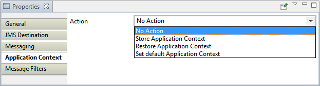
Figure 21: Application Context properties in the Input Port Properties panel
Action
Application Context can be used effectively by choosing the below options appropriately.
No Action
No Action is the default mode which is similar to not defining any particular action on the Application Context.
Store Application Context
Stores the Application Context to use it on a future instance.
Restore Application Context
Restores the Application Context which was stored previously.
Set Default Application Context
Uses the default Application Context instead of the one created separately
Message Filters
Messages can be filtered by providing a specific name and value to it under the Name and Value columns respectively.
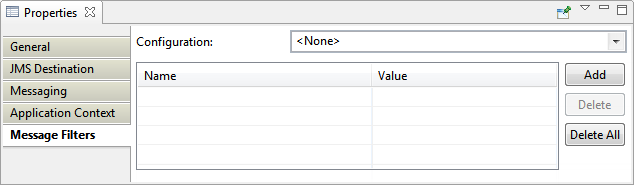
Figure 22: Message Filters properties in the Input Port Properties panel
Input port configured with specific values accepts only those messages that match the criteria specified in the Message Filter. If the message content does not match the criteria, the message is discarded.
Output Port Properties
Output port properties appear in the Properties pane when an output of a component instance is selected.
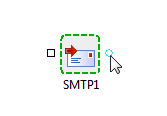
Figure 23: Output port properties selected/highlighted
Output port properties for an SMTP component are shown below.
General
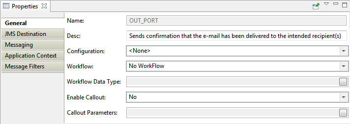
Figure 24: Output port General properties for a sample component instance
General Properties of Output Port have the same functions as that of the General Properties of Input Port.
JMS Destination
This group contains properties related to destinations created for the ports of the component. For more information, refer to JMS Destination section under Input Port Properties.
Messaging
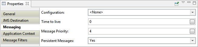
Figure 25: Messaging properties in the Output Port Properties panel
Time to Live
Specifies the time in milliseconds for which the message is available from the system after it is sent from the producer. The message is discarded on the expiration of this time. 0 (zero) milliseconds indicate infinite lifetime.
Example: Consider an application contains four component instances. Value for this property is set to 30000 milliseconds on the output port of the first component instance. This means, once the message is sent on the output port of first component instance, the message should be consumed by the fourth component instance in 30 seconds. If it is not consumed in 30 seconds, then the message will be lost and will never reach the fourth component.
Message Priority
The priority of the message sent; can be any integer value from 0 (zero - lowest) to 9 (nine - highest). The default priority is 4.
Persistent Messages
Specifies whether the producer on this port sends persistent messages or not. If this property is set to yes, all messages are persisted to message store. If this property is set to no, the messages are not persisted and there may be message loss noticed during the HA failover of the Peer Server.
Preventing message loss
To avoid message loss in Fiorano Event Processes, change the following properties -
- On each output port, set the value of property Persistent to yes.
- On each route, set the value of property Durable to yes.
- On each input port that is a topic, set the value of property Durable Subscription to yes.
- Whenever a JMS* component is used, make sure all messages sent are persistent and all subscriptions to topics are durable. These properties can be set in CPS of JMS components.
Components with implicitly defined JMS messaging properties
Some of the less used components in Fiorano have Acknowledgement Mode, Transaction Type, and Transaction Size implicitly defined and will not pick the values from the input port.
| Component | Acknowledgement Mode | Transaction Type | Transaction Size |
|---|---|---|---|
| Aggregator | AUTO_ACKNOWLEDGE | false | 1 |
| Chat | AUTO_ACKNOWLEDGE | false | 1 |
| DiskUsageMonitorService | AUTO_ACKNOWLEDGE | true | 1 |
| Display | AUTO_ACKNOWLEDGE | false | 1 |
| ExceptionListener | AUTO_ACKNOWLEDGE | false | 1 |
| Feeder | AUTO_ACKNOWLEDGE | false | 1 |
| HTTPReceive | AUTO_ACKNOWLEDGE | false | 1 |
| HTTPStub | DUPS_OK_ACKNOWLEDGE | false | 1 |
| Join | AUTO_ACKNOWLEDGE | from command line | 1 |
| SAPR3Monitor | AUTO_ACKNOWLEDGE | false | 1 |
| Sleep | AUTO_ACKNOWLEDGE | false | 1 |
| Timer | AUTO_ACKNOWLEDGE | true | 1 |
| WSStub | DUPS_OK_ACKNOWLEDGE | false | 1 |
| XMLVerification | AUTO_ACKNOWLEDGE | true | 1 |
Application Context
In the Output Port Application Context, you have an option to choose the Component Instance from the Configuration drop-down if it was saved after creating the Application Context. Rest of the options are the same as in Input Port properties.
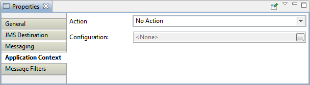
Figure 26: Application Context properties in the Output Port Properties panel
Message Filters
Refer the content in Message Filters under Input Port properties.
Configuration Property Sheet (CPS)
To view/customize the configuration attached to a component, use any one of the two options below in the Orchestrator:
- Double-click the component.
- Right-click the component and click Configure.
Managed Connection Factory
Connection Properties
Use Connection details from input
The parameters to create the connection can be specified in the input message when this property is selected. If this property is selected the validation errors in the managed connection factory panel of the CPS are treated as warnings.
Connection Pool Params
Defines the connection pool settings for the component. Creating a connection to external systems like Database or FTP Server or HTTP Server is typically a resource extensive and time-consuming process. Configuring a connection pool reduces the overhead of creating a connection on each request.
Click the ellipsis button  to launch an editor to configure connection pool parameters as shown in the figure below.
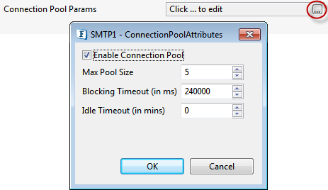
Figure 27: Connection pool configurations
Enable Connection Pool
If this property is selected, the connections created are cached in a pool for subsequent use. When the connection pool is disabled it implies that the connection should not be cached and a new connection will be created for each request.
Enabling connection pool property will reduce the time spent in creating a new connection for every input request.
Properties Max Pool Size, Blocking Timeout, and Idle Timeout are enabled only when this property is selected.
Max Pool Size
The maximum number of connections that can be cached in the pool.
Blocking Timeout (in ms)
The time in milliseconds after which the call to fetch a connection from the pool will timeout if there is no unused connection available. A connection will not be created after the timeout.
Idle Timeout (in mins)
Specifies the maximum time (in minutes) that an idle (unallocated) connection can remain in the pool before being removed to free resources.
Proxy Settings
Configure the properties to define a Proxy Server. Click the Proxy Settings ellipses button ![]() to launch an editor to configure proxy configurations as shown below.
to launch an editor to configure proxy configurations as shown below.
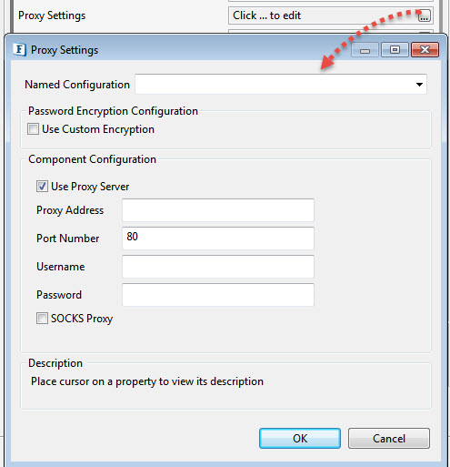
Figure 28: Proxy configurations
Use Proxy Server
Select this option if the connection has to be established using a proxy server. Properties Proxy Address, Port Number, Username, Password and SOCKS Proxy.
Proxy Address
The IP address or the host name of the machine where the proxy server is running.
Port Number
Port number on which the proxy server is running.
Username
The user name to log into the proxy server.
Password
Password for the user name provided.
SOCKS Proxy
Enable this property to use SOCKS protocol to connect to the proxy server.
SSL Security
Click the SSL Security ellipsis button to launch the editor to set SSL configurations.
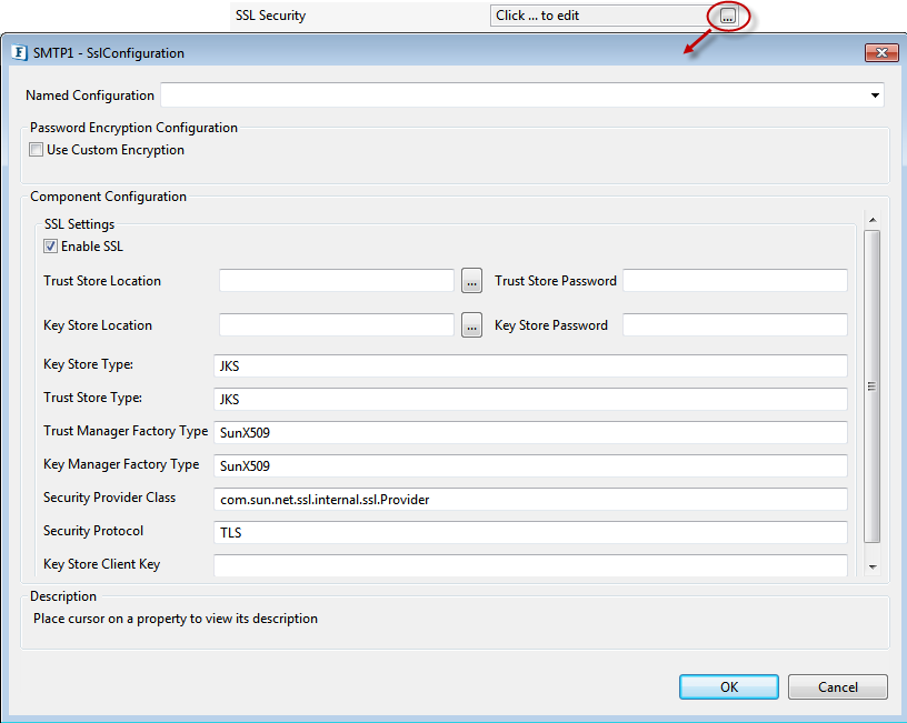
Figure 30: SSL configurations
Enable SSL
Select this option to enable SSL Settings. Rest of the properties in this editor are enabled and configurable only when this property is checked.
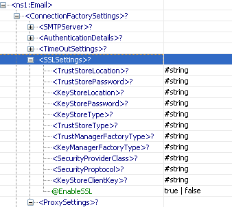
SSL Settings
| Property | Description |
|---|---|
| Trust Store Location | Location of the trust store file. TrustStore is a file where digital certificates of trusted sites are stored and retrieved for authentication during an SSL connection. TrustStore is used to authenticate a server in SSL authentication. |
| Trust Store Password | Password of the specified trust store. |
| Key Store Location | Location of the key store file. The KeyStore is used by the component for client authentication. |
| Key Store Password | Password to access the private key from the keystore file. |
| Key Store Type | Type of the Key Store whose location is specified by Key Store Location. For Java keystore file format, this property has the value jks (or JKS). You do not normally specify this property, because its default value is already jks . |
| Trust Store Type | Type of Trust Store whose location is specified by property Trust Store Location. For Java keystore file format, this property has the value jks (or JKS). You do not normally specify this property, because its default value is already jks . This value is optional. |
| Trust Manager Factory Type | Algorithm for the Trust Manager Factory. |
| Key Manager Factory Type | Algorithm for the Key Manager Factory. |
| Security Provider Class | Determines Security provider class. |
| Security Protocol | Determines Security protocol. |
| Key Store Client Key | Determines Key Store Client Key. |
Interaction Configurations
Pre/Post Processing XSL Configuration
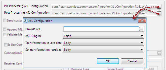
Figure 32: Pre/Post Processing XSL Configuration properties
Pre Processing XSL Configuration: Pre Processing XSL configuration can be used to transform request message before processing it.
Post Processing XSL Configuration: Post Processing XSL configuration can be used to transform response message before sending it to the output port.
XSL Configuration
Properties under XSL Configuration are described in the following sections.
Provide XSL
Provide XSL to be applied on the message for transformation.
XSLT Engine
When this property is chosen as 'other' along with Transformer factory class property, it determines the transformer implementation that should be used to perform the transformation.
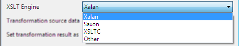
Figure 33: XSLT Engine properties
Xalan (2.7.0) and Saxon (8.4) transformer implementations are bundled with Fiorano environment for performing transformations.
Xalan
Xalan implementation (org.apache.xalan.processor.TransformerFactoryImpl) is used to perform transformation.
Saxon
Saxon implementation (net.sf.saxon.TransformerFactoryImpl) is used to perform transformation.
- Other
This option should be used when a custom transformer implementation has to be used. Selecting this option shows property Transformer factory class which can be used to provide the transformation factory implementation that should be used.
Transformation Source Data
This property is used to apply transformation source to a particular part of the input message.
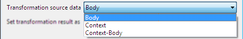
Figure 34: Transformation source data properties
- Body: Select if the transformation is to be applied on the Body of the input message.
- Context: Select if the transformation is to be applied on the Application Context of the input message.
Body-Context: Select if the transformation is to be applied on the both Body and Application Context of the input message.
Set Transformation result as
This property is used to set transformation result to a particular part of the output message.
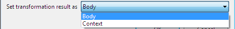
Figure 35: Set transformation result as properties
- Body: Select if the transformation result is to be set to the Body of the output message.
- Context: Select if the transformation result is to be set to the Application Context of the output message.
Process Message Based On a Property
The property helps components to skip certain messages from processing.
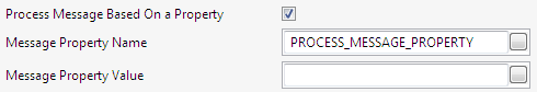
Figure 36: Process Message Based On a Property settings
Enable this property If the component needs to process a message based on a condition which will be validated based on its properties. The conditions can be specified using the properties described below.
Message Property Name
Property name of the message from where the value needs to be fetched to evaluate.
Message Property Value
Value of the message property.
For a given message, the condition is met only if the property specified in "Message Property Name" has the value specified in "Message Property Value". If the incoming message does not satisfy the condition, then the component indiscriminately forwards the message to its output port without processing it.
This property will be useful when sequencing has to be maintained between heterogeneous messages.
Example
In an Event Process that is configured to listen for multiple types of HL7 messages using WSStub microservice, which forwards them using different protocols based on the HL7 message type and inserts it into database, only the forward action is successful. Generally, parallel flows are defined for each HL7 message type, route selectors used to identify the flow and thereby message is sent out of the parallel flow to the DB component.
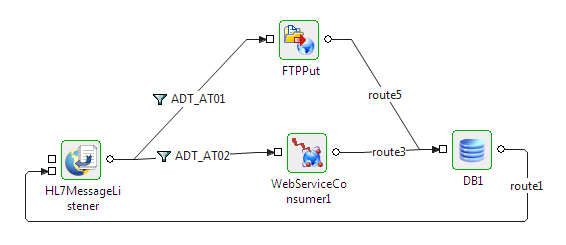
Figure 37: Event Process composed as a normal parallel flow
It is difficult to maintain order at the DB component input port in above flow. To maintain the order, process all the messages sequentially as shown in the figure below and configure the Process Message Based on Property based on the HL7 message type; only the required components will process, others just forward the message to its output port.
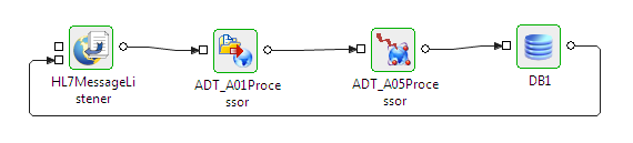
Figure 38: Event Process composed with the property enabled in the HL7 microservice
Validate Input
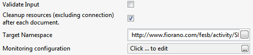
Figure 39: Common configurations in Interaction Spec panel
This property determines whether the input message has to be validated against the schema defined on the input ports.
- If enabled, input messages are validated against the schema defined on the input port on which the message is received.
- If disabled, input messages are not validated.
Cleanup resources (excluding connection) after each document
A component creates various objects to process business logic. Some of these objects are connection objects or are related to connection where as other objects are not related to connection but are required to process business logic. Holding these objects in-memory all the time will make lesser memory available that can be freed and deleting these objects to free up space results in higher processing time as the objects have to be recreated. Hence, the objects related to business logic can be removed from time to time.
- If enabled, objects that are not connection-related are not destroyed and are reused for each request.
- If disabled, objects that are not connection-related are destroyed and recreated for each request. When a connection object is destroyed, all objects are recreated on subsequent request.
Target Namespace
Two or more XML schema having same namespace will cause problems if there are elements which are defined with same name. Schema set on the input and output ports of the component are in some created by the component. To avoid the clash of elements from different schema, the schema generated by the component use the value provided for this property to compute the namespace for input or output schema.
Monitoring Configuration
When monitoring is enabled for a component, it publishes USER_EVENTs containing the following statistics, which are sent to FPS_USER_EVENTS_TOPIC at the configured intervals of time:
- Minimum execution time: The minimum amount of time taken to process any message during the last publish interval.
- Maximum execution time: The maximum amount of time taken to process any message during the last publish interval.
- Count: Number of messages processed during the last publish interval.
- Throughput: Rate at which messages are processed during the last publish interval.
Click the ellipsis button to launch an editor to configure Monitoring configuration.
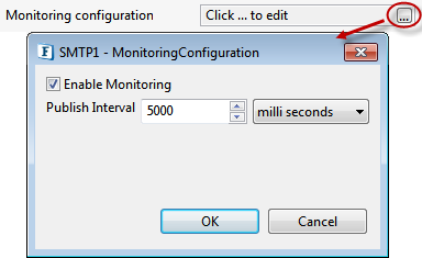
Figure 40: Monitoring configurations in Interaction Spec panel
Enable Monitoring
Select the check box to enable monitoring for request execution time.
Publish Interval
The time interval after which monitoring statistics are computed and sent.
Enabling ListenForUserEvents parameter for Monitoring Performance
To display the monitoring statistics in Dashboard, apart from enabling Monitoring in the CPS, the parameter ListenForUserEvents in FES profile needs to be enabled which can be done from eStuido or the Dashboard as illustrated in the following sections. This property decides whether or not the Enterprise Server listens to the monitoring events published by component instances.
eStudio
- Open Profile Management and go to FES under Profiles.
- Navigate to FES > Fiorano > Esb > Events.
- Click FESEventsManager to open the Properties of FESEventsManager window on the right side.
Under ComponentInstance Configuration section, select the ListenForUserEvents checkbox.
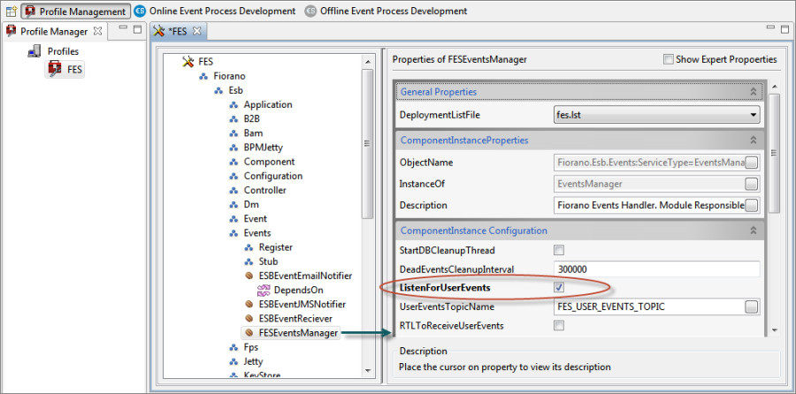
Figure 41: Enabling Dashboard Monitoring option through eStudio
Dashboard
- Go to Advanced Properties property under Advanced Properties tab present in the Navigation Panel.
- In the Configure Advanced Property window, expand Enterprise Server>Events Manager.
- Under Action column, click the Change button corresponding to the Attribute Name: ListenForUserEvents.
- Change the value to "true" from the ListenForUserEvents drop-down and click OK.
- Click Save Configuration button in the Save Changes dialog box and notice the change in the Attribute Value parameter.
- Restart Server to bring the changes into effect.
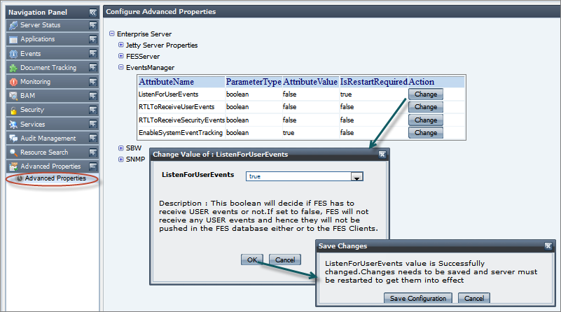
Figure 42: Enabling Dashboard Monitoring option through Dashboard
Threadpool Configuration
This property is used when there is a need to process messages in parallel within the component, still maintaining the sequence from the external perspective.
- This needs to be used only in such circumstances.
- If sequential processing is not required, please use sessions on the input port.
Click the Threadpool Configuration ellipses button to configure the Threadpool Configuration properties.
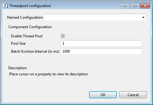
Figure 43: Threadpool Configuration properties
Enable Thread Pool
Enable this option to configure the properties that appear as below.
Pool Size
The number of requests to be processed in parallel within the component. Default value is '1'.
Batch Eviction Interval (in ms)
Time in milliseconds after which the threads are evicted in case of inactivity. New threads are created in place of evicted threads when new requests are received. Default value is '1000'.
Scheduler Configurations
A component can be scheduled to execute a specific request at configured intervals of time. When the component is configured to run in Scheduler mode, the component will not have input port (separate input need not be sent to the component in order to send message). However, messaging properties that are usually configured on the input port can be configured in Transport Configurations panel.
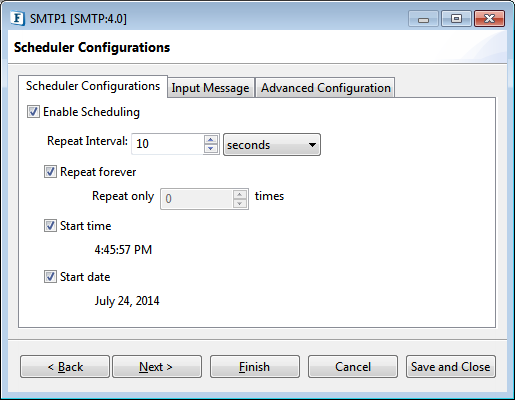
Figure 44: Scheduler configurations panel
Scheduler Configurations tab
Enable Scheduling
Select the check box to run the component in the scheduling mode.
Repeat Interval
Specifies time interval between successive requests.
The units of time available are:
- milli seconds
- seconds
- minutes
- hours
- days
Repeat forever
If this option is enabled, then the number of times the input request is executed will be infinite.
Repeat only
Specifies the number of times the input request is executed.
Start time
The polling start time. If the specified start time is earlier than the component start time, the first schedule will happen at the next scheduled time. For example, start time is 08:00:00, poll interval is 30 minutes, and component starts at 8:10:00, the first schedule will happen at 08:30:00.
Start date
The polling start date. If the specified start date is earlier than the component start date, then it will be ignored and input messages are sent at next scheduled date.
Input Message
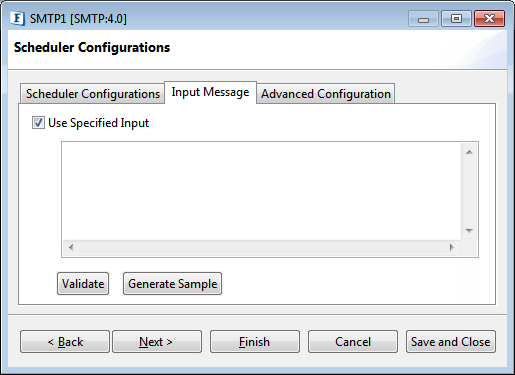
Figure 45: Input Message tab in the Scheduler Configurations panel
Use specified Input
Select the check box to configure input that is repeatedly executed.
- Validate: Validates the specified input against the structure specified on the input port.
- Generate Sample Input: Generates the sample input for the structure specified on the input port.
Advanced Configuration
Advanced scheduling information can be configured in the Scheduler Configuration panel.
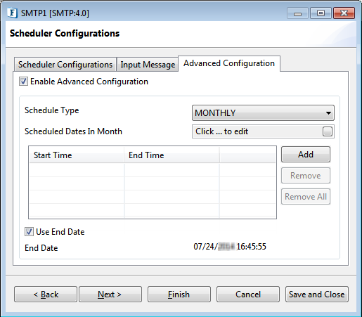
Figure 46: Advanced Scheduling configuration
Enable Advanced Scheduling
This option can be chosen if advanced scheduling options like scheduling on specific days, dates and during certain time periods needs to be done.
Schedule Type
The scheduling type can be chosen depending on the way the scheduling of messages needs to be controlled.
The different scheduling types and their working are as below.
- DAILY: The message is sent every day between the start and end time as defined in the sessions table. The times have to be in hh:mm:ss format.
- WEEKLY: The message is sent on predefined days of a week. The days in week can be chosen on clicking the ellipsis against the property Scheduled Days in Week. The messages are sent only during the intervals defined by the sessions panel.
- MONTHLY: The message is sent on predefined dates in a month. The days in week can be chosen on clicking the ellipsis against the property Scheduled Dates in Month. The messages are sent only during the intervals defined by the sessions panel.
Scheduled Dates In Month (Schedule Type - MONTHLY)
Click the button against the property to specify the dates in the Editor. Dates moved to the Included Entries section are considered as the scheduled dates.
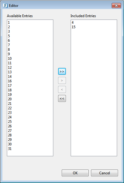
Figure 47: Editor to provide Scheduled Dates In Month
Scheduled days in week (Schedule Type - WEEKLY)
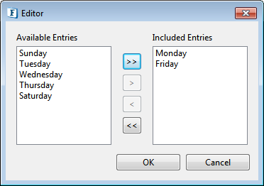
Figure 48: Editor to provide Scheduled days in week
Start Time
Provide the Start Time and End Time by clicking Add button and then entering the timings.
Use End Date
When this option is chosen, the scheduling will stop on the date as defined against End Date. The date has to be in MM/dd/yyyy HH:mm:ss format.
Transport Configurations
Transport Configurations panel is used to configure messaging properties when the component is configured in Scheduling mode.
After selecting the Enable Scheduling check box in the Scheduler Configuration panel, click Next to configure Transport properties in Transport Configurations panel.
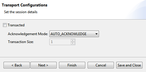
Figure 49: Transport configurations panel
Transacted
For information on this property, refer to section Transacted in Input Port Properties.
Acknowledgement Mode
The Acknowledge modes available are:
- AUTO ACKNOWLEDGE
- CLIENT ACKNOWLEDGE
- DUPS OK ACKNOWLEDGE
For information on acknowledgement modes, refer to section Acknowledgement Mode in Input Port Properties.
Transaction Size
For information on this property, refer to section Transaction Size in Input Port Properties.
Error Handling
Errors that occur in the component are classified into five categories – JMS Error, Response Generation Error, Request Processing Error, Connection Error and Invalid Request Error. Actions that have to be taken when an error occurs are defined in the Error Handling panel.
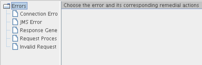
Figure 50: Error handling
Connection Error
This property in Error Handling Panel will be visible only if the Managed Connection Factory panel is present. Presence of Managed Connection Factory implies that the component makes a connection to external system.
Example: Components like FileReader and FileWriter do not create any connections and hence they do not have this property in the CPS.
Errors that occur because of the connection to an external system cannot be made or because the connection to an external system is lost are categorized under the category
Connection Error
Example: Trying to connect to an external web site when the network connection is not active.
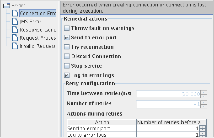
Figure 51: Available actions for Connection Error category
Remedial Actions
Actions that can be taken when a Connection Error occurs are as explained below.
- Send To Error Port: When an invalid input is given to the component, it sends the error on the ON_EXCEPTION output port of the component. By default, ON_EXCEPTION port is present in all components that support error handling. If this option is unchecked, then the Retries before sending error property in Advanced Settings group is disabled.
- Try reconnection: The component will re-execute the input request with a new connection, if this action is enabled. The number of times it should try and the time interval between two successive retries can be configured in Advanced Setting Panel of this panel. Configuring for retries is explained in Retry Configuration section.
Discard Connection: The component removes the connection from the connection pool as soon as a connection error occurs. If the processing of input request fails due to connection error then component will discard that connection object. The component will try with another connection object from the connection pool, if there are no connections in the connection pool then the component will create a new connection, and this connection is used to process the input request.
Stop Service: The component is stopped when an error occurs if this action is enabled.
JMS Error
Errors that occur in transport (JMS)
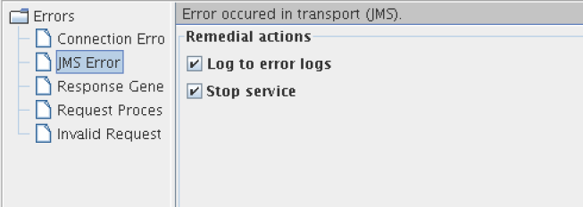
Figure 52: Available actions for JMS Error category
Remedial Actions
Actions that can be taken when a JMS Error occurs are as explained below:
- Log to error logs: Logs the exception and trace to error logs.
- Stop service: The component is stopped when an error occurs if this action is enabled.
Response Generation Error
Errors that occur while building a response for the processed request.
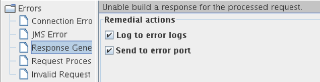
Figure 53: Available actions for Response Generation Error category
Remedial Actions
Actions that can be taken when a Response Generation Error occurs are as explained below:
- Log to error logs: Logs the exception and trace to error logs.
Send to error port: when an invalid input is given to the component, it sends the error on the ON_EXCEPTION output port of the component if this action is enabled. By default, ON_EXCEPTION port is present in all components that support error handling.
Request Processing Error
Request Processing Errors are categorized based on the following conditions:
- The error occurs after input message is successfully parsed and understood.
- The error is not a result of connection problems.
Example: In case of FTPGet, a Request Processing Error occurs when the specified file (to be downloaded) in the input request is not present in FTP Server.
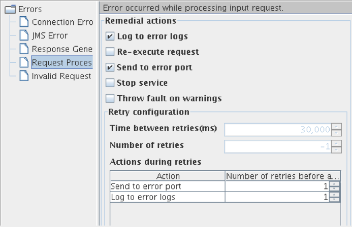
Figure 54: Available actions for Request Processing Error category
Remedial Actions
Actions that can be taken when a Request Processing Error occurs are as explained below:.
- Log to error logs: Logs the exception and trace to error logs.
- Re-execute Request: The component will re-execute the input request if this action is enabled. Configuring for retries is explained in section Retry Configuration section. This action should be enabled only for errors that may be rectified over time.
Example: Error in file reader because a file is not found. If the required file should be placed by another process, then the file not found error can be rectified over time and hence can be retried.
- Send To Error Port: When an invalid input is given to the component, it sends the error on the ON_EXCEPTION output port of the component. By default, ON_EXCEPTION port is present in all components that support error handling. Retries before sending error property in Advanced Settings group is disabled if this option is unchecked.
- Stop Service: The component is stopped when an error occurs if this action is enabled.
- Throw fault on warnings: In some cases, a problem in the component which is not severe is treated as a warning. Such warnings are just logged by default. The component will treat such warnings as errors, if this property is enabled.
Example: When the FileReader is configured to read files with a particular pattern for file names, a warning is logged if there are no files whose names match the pattern configured. If the FileReader is polling a directory, then it is an inherent assumption that files are not always present and hence treating it as warning is appropriate. But if the file reader is not in scheduler mode, then absence of files has to be treated as an error.
Invalid Request Error
Errors that occur when parsing the input request are categorized under Invalid Request Error. Remedial actions are different for EDBC and BC components.
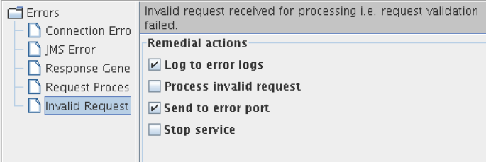
Figure 55: Available actions for Invalid Request Error category
EDBC Components
Remedial Actions
- Log to error logs: Logs the exception and trace to error logs.
- Process invalid request: Do not stop processing in case request is invalid. Continue Processing.
- Send To Error Port: When an invalid input is given to the component, it sends the error to the ON_EXCEPTION output port of the component. By default, ON_EXCEPTION port is present in all components that support error handling. If this option is unchecked, then the Retries before sending error property in Advanced Settings group is disabled.
- Stop service: The component is stopped when an error occurs if this action is enabled.
BC Components
Remedial Actions
Actions that can be taken when an Invalid Request Error occurs.
- Send To Error Port: When an invalid input is given to the adapter, it sends the error on the ON_EXCEPTION output port of the component. By default, ON_EXCEPTION port is present in all components that support error handling. Retries before sending error property in Advanced Settings group is disabled if this option is unchecked.
- Do not stop service: If this property is not checked, when an invalid input is sent to the component, the component will be stopped immediately. This property is checked by default.
Example: In case of SMTP, if the input message is not valid according to the schema set on its IN_PORT, an exception occurs and the component will be stopped only if this property is unchecked.
Retry Configuration
When Re-execute Request is enabled for Request Processing Error or when Try Reconnection is enabled for Connection Error, the Advanced Settings group containing configurations for retries is visible.
- Time between retries(ms): The time interval between two successive retries.
- Number of retries: The number of times the component should retry the request. This property is enabled only if Infinite check box is unselected.
- Infinite: If the check box is selected, the component will continuously retry the request until the request is process successfully. when this option is selected, the property Number of retries is disabled and its value is ignored.
- Retries before sending error: This property is enabled only if Send To Error Port action is enabled. If Send To Error Port action is enabled and if the value for this component is a number n, then the component sends an error on the ON_EXCEPTION port after every n retries.
Schema Editor
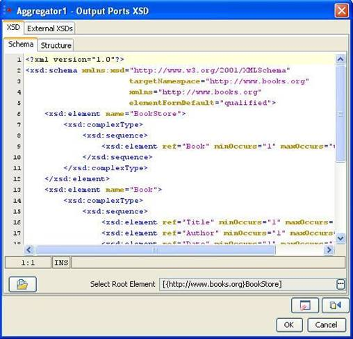
Figure 56: Schema Editor
Schema Editor is used to configure schemas that are required for the functionality of a component.
In general,
- XSDs and DTDs can both be provided in the schema editor. Some components allow only XSDs.
- Only one root element can be selected. Some components allow selecting multiple root elements.
- When a DTD is provided in the schema editor, the External XSDs tab is disabled.
XSD
Schema
Schemas that are present on the file system can be loaded by clicking on Load button ![]() or the XSD/DTD can be provided in the text area in the schema tab shown in figure 48. This opens a file browser which enables navigation to the required schema on the file system. The file type can be chosen as XSD or DTD in the filechooser.
or the XSD/DTD can be provided in the text area in the schema tab shown in figure 48. This opens a file browser which enables navigation to the required schema on the file system. The file type can be chosen as XSD or DTD in the filechooser.
Root element can be selected by clicking on Select Root Element button ![]() . A list containing all the elements present in the schema will be displayed as shown in Figure 49. A root element (multiple root elements, in some cases) should be selected from that list of elements. The selected root element(s) will be displayed in the schema editor next to Select Root Element text.
. A list containing all the elements present in the schema will be displayed as shown in Figure 49. A root element (multiple root elements, in some cases) should be selected from that list of elements. The selected root element(s) will be displayed in the schema editor next to Select Root Element text.
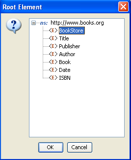
Figure 57: Selection of root element
Structure
The structure tab displays a tree structure of the schema provided as shown below. The structure depends on root element.
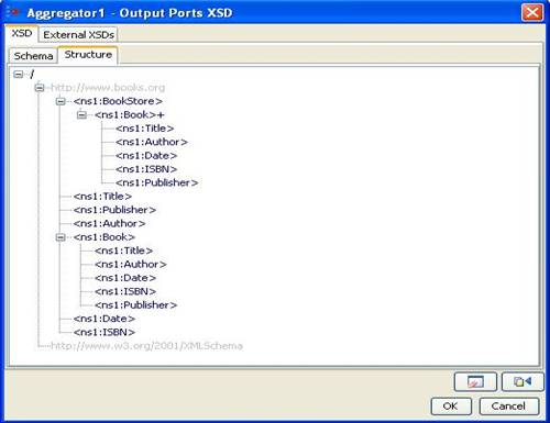
Figure 58: Structure of the schema when no Root Element is chosen
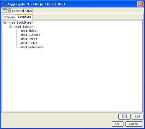
Figure 59: Structure of the schema when Bookstore is chosen as Root Element
The structure of the entire schema is displayed if none of the root element is selected. If root element is selected (as 'Bookstore' in the figure above), the structure of that element is displayed.
External XSDs
If there are any imported schemas in the schema provided in XSD-Schema tab, they can be resolved by adding them as the external XSDs here. Any number of external schemas can be added here.
Schemas provided as external XSDs must have target namespace defined.
Click the Add button to add the external schema. Select an option from Manual or Load from File.
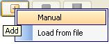
Figure 60: Adding external schema
- Manual - The text editor on the right is editable only when Manual option is selected. The schema has to be provided manually in the text editor.
- Load from File - Opens a File Chooser to browse the required external schema.
After loading the schema in the text editor, click the Save button ![]() to save the schema. The schema will be added to the list of external XSDs only when it is saved.
to save the schema. The schema will be added to the list of external XSDs only when it is saved.
To remove a schema, select the corresponding namespace and click Remove button ![]() .
.
To view a schema, select the corresponding namespace and the schema can be viewed in the text editor.
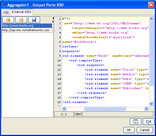
Figure 61: Configuring external schema
Clear ![]()
On clicking Clear button, the schema, external schemas, root element and structure present in the schema editor will be cleared.
Fetch from Connected Source ![]()
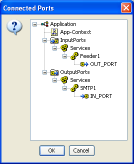
Figure 62: List of connected ports from which schema should be fetched
On clicking Fetch from Connected Source button, a list of ports (which have schema set on them) of the components connected to this component are displayed. Application Context of the event process is also listed, if defined. On selecting one of the ports or application context, the schema present will be set as schema in the schema editor.
Schema Repository
Schema Repository is used to store schemas that are imported in schemas used by different components/event processes. The imported schemas referred from anywhere in an Event Process/component can be stored here so that they are resolved even when they are not added explicitly. Hence, schemas which are imported across multiple event processes/components can be stored in the schema repository.
Adding Schema
To add schemas to the Schema Repository, perform the following steps.
- In Studio, navigate to Tools > Schema Repository. This opens a Schema Repository editor using which schemas can be added to schema repository.
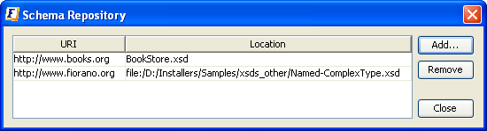
Figure 63: Schema repository editor - Click the Add Button to add schemas to the repository, Customize Add... editor.
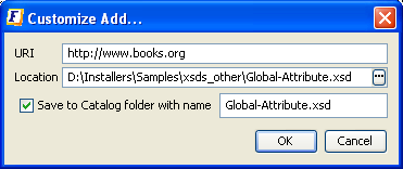
Figure 64: Adding XSD to the schema repository - Click the ellipsis button
 to browse the required XSD.
 - Select an XSD and click OK
The values URI, Location, schema name will be automatically updated.- The URI value should not be an empty field. In case, if the schema has a target namespace, URI should be same as the target namespace of the XSD.
- The Location field displays the absolute path of the schema file.
- If the schema is to be copied and saved in the location <FIORANO_HOME>/xml-catalog/user, select the field Save to Catalog folder with name and specify a name with which the file has to be saved.
- If Save to Catalog folder with name is not selected, the file is not copied to the location <FIORANO_HOME>/xml-catalog/user and will be referred from its original location.
- Click OK to close Customize Add editor.
A new row specifying the URI and Location of the XSD will be added in the table.- To remove a schema from the schema repository, select a row from the table and click Remove.
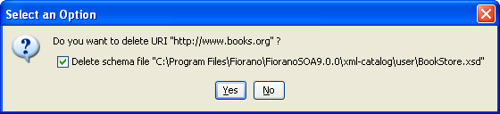
Figure 65: Removing XSD from the schema repository - The option 'Delete schema file' specifies whether to delete the file from the system or just to remove the schema from xml-catalog. Select the check box to remove the file completely.
- In case, if the file is not copied to <FIORANO_HOME>/xml-catalog/user, the file will be deleted from its original location if this option is selected.
- To remove a schema from the schema repository, select a row from the table and click Remove.
XPath Editor
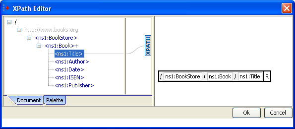
Figure 66: XPath Editor
XPath Editor can be used for specifying path expressions to identify nodes in an XML document and for specifying conditions. The list of elements from schema provided are shown in the left panel of the editor. An XPath Editor with sample schema is shown below.

Figure 67: Adding a constant in XPath Editor
An element can be selected by simple drag and drop onto the right panel. An XPath expression may consist of different constant values, functions or/and operators. These can be added easily by right clicking on the right panel and selecting the option based on the requirement.
Adding a Function
A function can be added either by right clicking on the right hand side panel --> Add Function or by selecting from the list available in the palette tab which is present in the left panel as shown below.
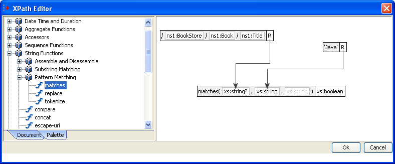
Figure 68: XPath Editor – Palette containing different XPath functions
A string function matches which takes two arguments and returns a boolean value is shown in the above figure.
Adding a Constant value
Supported types of constants are String, Boolean, Numeric, Date-Time, and Duration.
Example: Addition of a boolean value can be done as described below
- Right-click the right panel. Select Add Constant > Boolean Value.
- Select the value as shown below.
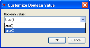
Figure 69: Adding a boolean constant
Addition an Operator
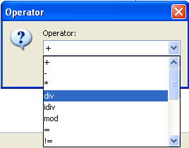
Figure 70: Adding an operator
- Right-click the right panel. Click the Add Operator
 button.
 - Select the operator as shown in the above figure.
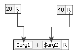
Figure 71: Add ![]() operator
operator
The figure above illustrates a sample Xpath expression using a '+' operator. It contains two numeric constant values which are passed as arguments to the operator.
Named Configurations in CPS
Named Configurations may be used in eStudio CPS of components. Configurations can either be loaded from or saved to the repository from CPS itself.
If named configuration is not to be used in the CPS, the text box against Named Configuration shown in the below figures should be left blank and no Named Configuration will be used.
Load Named Configuration
Named Configurations which are created earlier either from the Configuration Repository view or from the CPS itself can be re-used in other service instances.
To view all the named configurations of a particular service or resource type, use the drop-down in named configurations editor present in the CPS. A list of all configurations of similar type present in the repository is shown. Select a configuration name from the list to use that named configuration in a given service instance.
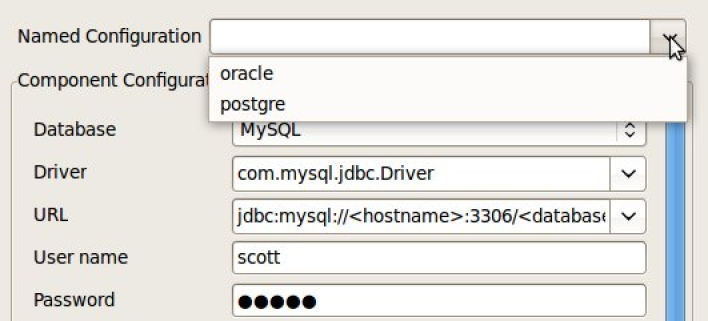
Figure 72: Load Named Configuration
After selecting the named configuration from drop down, the UI will be disabled and will not be able to edit the configuration.
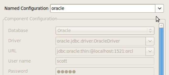
Figure 73: UI disabled after loading Named Configuration
Save Named Configuration
To save a new Named Configuration to the repository, specify a name against Named Configuration, which is not present in the drop-down list and provide the configuration details that need to be saved.
Click Save and Close button or Finish button in the CPS to save the named configuration to the repository.
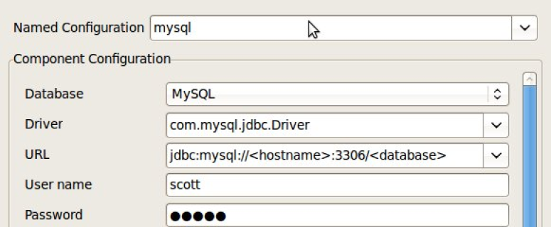
Figure 74: Save Named Configuration
Encrypt Decrypt Configuration
XML Messages received by and sent from components in event processes can be encrypted and/or decrypted so that sensitive data will be more secure and be protected from being accessible to everyone, and hence enable authorized usage.
This can be done by providing a global encryption key and selecting the elements in XML messages that are to be encrypted/decrypted in component configuration.
XML Message Encryption and Decryption
The first step in securing XML messages is to define an encryption key to be used across all event processes.
Adding Encryption Key
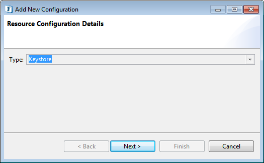
- In eStudio, navigate to Configuration Repository View and right-click the Resource button. Select Add Configuration to open the window for adding new Resource Configuration. Select the Resource type as MessageEncryptionConfiguration as shown in the figure below and click Next.
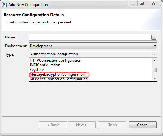
Figure 75: Add Resource Configuration - Provide the encryption key password (any string) and XML Block Encryption Algorithm as below and click Finish. Supported XML Block Encryption Algorithms are AES128, AES256, TRIPLEDES.
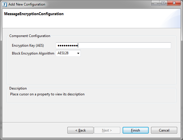
Figure 76: Provide Encryption Key and Algorithm
Configuring Components for Message Encryption
When enabled, in general, components will send messages coming out on OUT_PORT in encrypted form and those received on IN_PORT will be decrypted. However, some components which send messages to other servers after receiving them on IN_PORT, like WebServiceConsumer, can encrypt the message received on IN_PORT before sending it to the server and decrypt the message after receiving from the server before sending to OUT_PORT.
The components that support both encryption and decryption on both input and output ports are WSStub, WebServiceConsumer:5.0, WebServiceConsumer:4.0, SalesForce, HTTPAdapters:5.0, HTTPAdapters:4.0 and HttpReceive.
Selecting XML elements to encrypt
In the component CPS, which have single input and output ports, the configuration will be as below.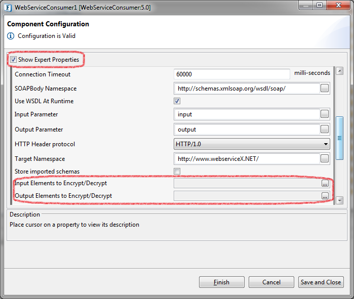
Figure 77: Encrypt/Decrypt properties in CPS
Enable Show Expert Properties to see properties Input Elements to Encrypt/Decrypt and Output Elements to Encrypt/Decrypt. Both have similar configurations.
Open the Property Editor by clicking on ellipsis button to select XML elements.
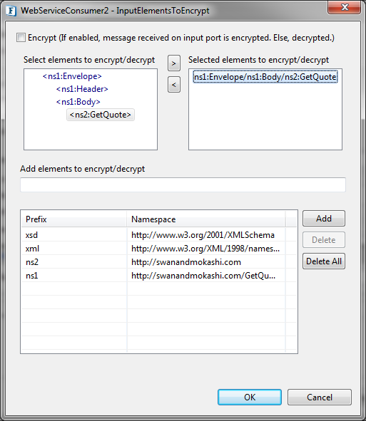
Figure 78: Select elements to encrypt/decrypt
Encrypt: Select this option if the message coming on to this port should be encrypted. Otherwise, the component assumes the message is already encrypted and so will be decrypted.
Select elements to encrypt/decrypt: The message will be either encrypted or decrypted only if there are any XML elements in Selected elements list.
Under Select elements to encrypt/decrypt, the schema structure of the input/output port is shown.
The encryption mechanism does not encrypt/decrypt the XML message as a whole but only the individual XML elements.
Select the elements which are to be encrypted or decrypted by clicking ![]() button.
button.
There is no need to select child elements if a parent element is selected. The parent element is encrypted as a whole.
Add elements to encrypt/decrypt: Some components may not have schema on ports. In that case, semi colon separated XPaths, similar to the one in Selected elements list, can be provided here.
Namespace Prefixes: A map of prefix versus namespace used in XPaths can be configured here.
In components with multiple ports, the configuration is similar to single port components except that the above configuration can be done for each individual port.
Navigate to Encrypt/Decrypt Configuration and click Refresh to populate the ports of the component.
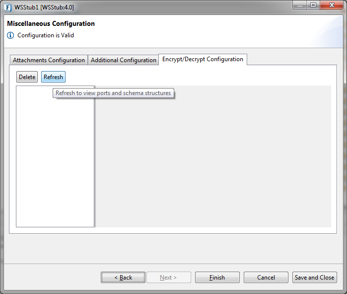
Figure 79: Components with multiple ports
Select the required port to populate schema structure. The rest of the configuration is the same as above.
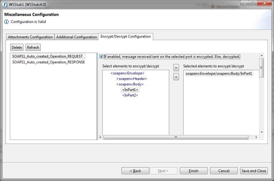
Figure 80: Select elements for each port
Sample Event Process demonstrating Message Encryption
- Create an Event Process with Feeder and Display.
- Configure Feeder with a schema. In the next page, select Encrypt Configuration tab and select XML elements to encrypt as described above.
- Adding MessageEncryptionConfiguration in Configuration Repository view is mandatory before launching the component.
- Launch the event process and send a message from Feeder to Display.
- A sample message received by Display where OutPart1 element is encrypted can be as below.
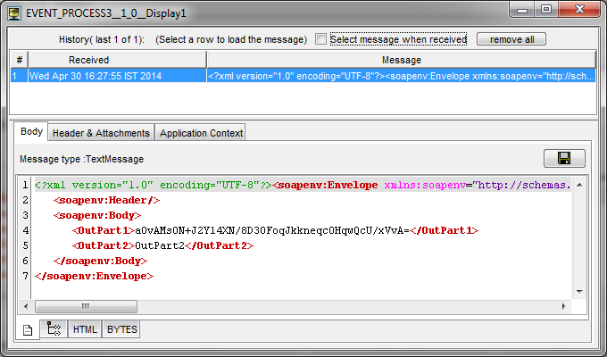
Figure 81: Sample encrypted message
Password Encryption
Adding KeyStore Configuration
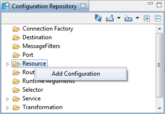
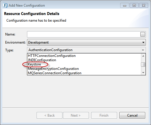
- In eStudio, open Configuration Repository panel and right-click Resource. Click Add Configuration to add new Resource Configuration. Select the Resource type as "Keystore" as shown below.
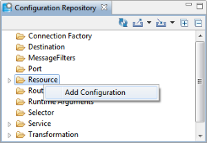
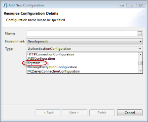
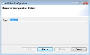
Figure 80: Adding Resource Configuration - Click Next to get the add AES Encryption Key. Enter any String of your choice (recommended minimum of 6 characters for better security) and click Finish to save the keystore which will be used as the key for encryption/decryption of data.
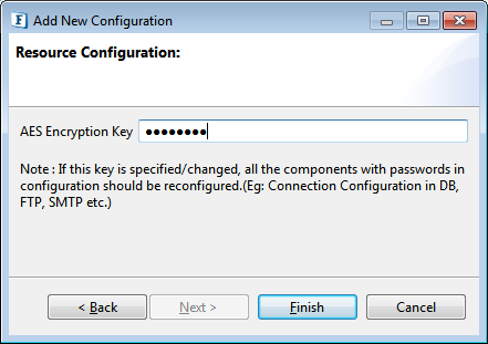
Figure 82: Adding Encryption Key
Custom Encryption of Passwords
Components in Fiorano Event Processes contain passwords of External Systems like Databases, FTP Servers as part of their configuration. Using this feature, users can use their own keys and algorithms to encrypt passwords.
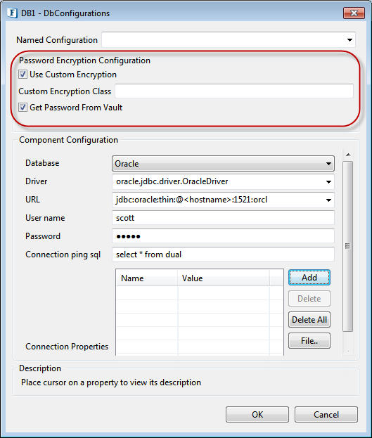
Figure 83: DB Configuration dialog box
Password Encryption Configuration
Use Custom Encryption
This feature enables you to use your own keys and algorithms to encrypt passwords. On selecting this check box, two prompts appear, asking for CustomClass and whether to get Password from vault.
Custom Encryption Class
Java Class which implements ICustomEncryptor has to given in Custom Class text box. You have to override methods encrypt(String) and decrypt(String), for encrypting and decrypting passwords respectively.
Get Password From Vault
If this check box is selected, you have to enter key instead of password in password field(s). getPasswdFromVault(String key) method from CustomClass (which is implementor of IcustomEncryptor) gets the passwords by taking keys as params.
Below is the sample class that reverses the password(s) and saves password(s) in configuration. Follow the below steps for testing:
- Compile the java file with including fiorano-utilj4 jar in classpath.This jar is at location {FIORANO_HOME}/framework/lib/fiorano-utilj4.jar
- After compiling, add the class to resources of that component.
- Right-click the component in Service Palette and click Edit.
- Under Deployement tab, add class file/jar(with compiled class) to resources; the input request gets executed.
External CPS Error with Solaris (solution)
To make External CPS (components like RESTStub, RestConsumer, XMLSplitter, Aggregator etc) work in Solaris operating system, make changes in java.security (location: $JAVA_HOME/jre/lib/security) as mentioned in the following link: http://ccortezsv.blogspot.in/2014/03/sunsecuritypkcs11configurationexception.html