Overview
This component is used to expose an Event Process or a part of Event Process as a Web Service deployed in the Peer Server. WSDL for the service deployed can be fetched when this component is running and the URL of the WSDL can be used by Web Service clients to access the Web Service. Each instance of the component hosts a single web service. The component can be configured in two ways:
- Manually defining the operations and related details in the UI
- Loading a predefined WSDL and editing the populated web service details if required
The WSDL generated for the component will differ from the WSDL provided in the following aspects:
- Endpoint address
- If the provided WSDL contains multiple services, only the selected service will be present
The component generates request, response and error ports for each operation present in the selected web service.
How it Works
During the component launch, following activities happen sequentially:
- It checks if a web service with the same web service name is already deployed.
- If no other service with the same name exists, the web service is deployed to the Jetty Server running in Peer Server that hosts the component.
- The web service deployed in the Jetty accepts requests from web service clients and sends the SOAP XML using internal JMS client to the request port of the operation thereby injecting the request into the Fiorano Event Process for processing the request.
- On processing the request, the response SOAP XML gets generated and is sent to the corresponding response/error ports.
- The web service receives the response from the internal JMS client and in turn sends the response as SOAP response to the client that made the request.
Configuration
The component can be configured using the Configuration Property Sheet (CPS).
Configuration panel
Configuration panel in the CPS allows Web Service configuration, FES Connection configuration, and Execution configuration. Each one is explained in the below sections.
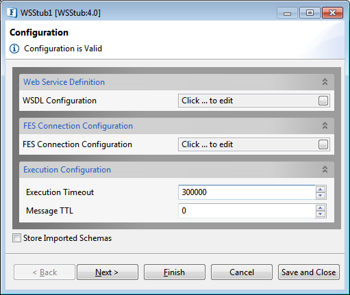
Figure 1: Configuration panel in CPS
Web Service Definition
WSDL Configuration
Click the button against the WSDL Configuration property to set up the configuration.
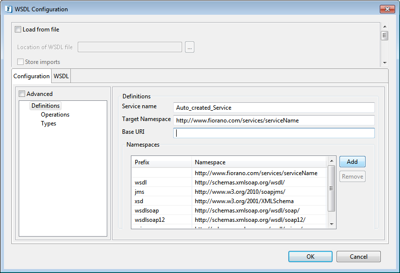
Figure 2: Configuration Property Sheet
This page is used to define the web service using a user interface for WSDL. You can create a WSDL by manually defining different aspects of the service or can load an existing WSDL and edit the configurations.
Loading From file
Existing WSDL file can be used to define the web service. To load an existing WSDL file, click the Load from file checkbox to show the options below.

Figure 3: Loading Existing WSDL
Location of WSDL File
The WSDL file can be loaded using the file dialog that opens up when the ellipsis ![]() is selected. The parent directory of the selected file is set as the base URI for this definition. It can be changed by clicking on the definitions node in Basic/Advanced view of the definition and changing the Base URI field (explained in following sections). If the loaded WSDL file has more than one service defined, then the user is prompted to select one service for configuration as shown in figure 3.
is selected. The parent directory of the selected file is set as the base URI for this definition. It can be changed by clicking on the definitions node in Basic/Advanced view of the definition and changing the Base URI field (explained in following sections). If the loaded WSDL file has more than one service defined, then the user is prompted to select one service for configuration as shown in figure 3.

Figure 4: Service selection
Store Imports
This option can be selected if the WSDL files imported in the loaded WSDL have to be stored on the Jetty server. The imported files will be stored at FIORANO_HOME\esb\server\jetty\fps\webapps\bcwsgateway\wsdls\<ServiceName>\imports and their paths in the WSDL are updated when the component starts and deleted when the component stops.
Using this option allows the web service clients to access the import WSDLs as well relative to the actual WSDL. However, for this option to work the imported files should be present in the location specified in Base URI field and that location should be accessible from the Peer Server on which the component will be launched.
If this option is not specified, the web service clients should be provided with a copy of all imported WSDLs, if required.
WS Definition Views
Details of the selected WSDL are shown in 2 different views—Advanced and WSDL.
- Advanced: Web service can be configured using the Advanced view, enabled or disabled, based on the expertise (explained further).
- WSDL: Details of the configuration in Advanced tab gets reflected in WSDL tab in XML format. The XML content can be edited by experts.
WSDL dependencies Tree
WSDL dependency tree shows the WSDL and all the imported WSDL referenced directly or indirectly from the main WSDL. Each node in the tree represents a WSDL and the WSDLs that are imported in the WSDL represented by the node are represented by its child nodes. Selecting a node in this tree will show the corresponding WSDL definition in the panel under it.
Editing or defining an imported WSDL is not presently supported. When a node representing an imported WSDL is selected (when you select from Type/Element under the Operation tab in the right panel), the panel will be in Read-only mode.
Advanced disabled (Checkbox cleared)
This view is recommended for those who are not experts to work with WSDL. In this view, webservice definition can be created with the knowledge of input, output and fault type (if any). The SOAP bindings and other necessary elements for WSDL are created automatically when an operation is added in this view.
The web service definition can be configured by selecting the nodes in the tree on the left side as shown in figure 4. When a node is selected in the tree, the corresponding configuration is shown in the right side pane.
Definitions
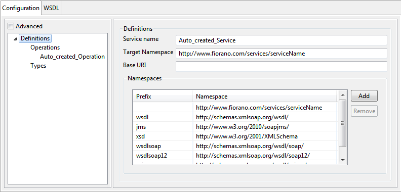
Figure 5: Definition Configuration
Service name
This field is used to specify the name of the service.
Target Namespace
This field is used to specify the target namespace of the WSDL that is generated.
Base URI
This field is used to provide the location from which the relative paths of imported WSDLs used in the selected WSDL will be resolved. By default, it is populated with the location where the WSDL is present. It should be edited to the correct location if required.
If Save Imports is selected, this location should be accessible from the Peer Server on which the component will be launched.
Namespaces
This table is used to assign prefixes to all namespaces that are used in the WSDL.
Types
The schemas which are necessary for defining the web services can be added in the view corresponding to the Types node.
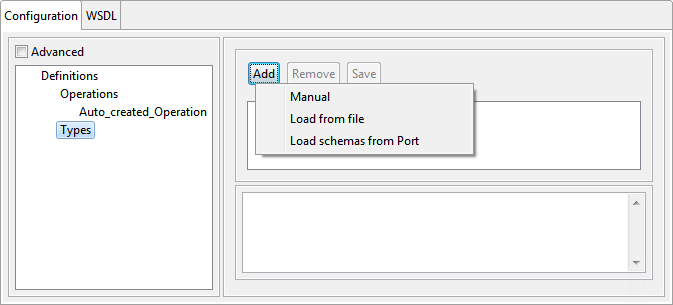
Figure 6: Types Configuration
The schema content can be loaded by clicking the Add button and then saving the content from your preferred source.
The schemas that are added will be shown in the editor on the right panel. When a schema is added, its target namespace and imported namespaces will be added to the WSDL with an auto-generated prefix. Imported/included schemas, if any, have to be added to the Schema Repository.
Adding an Operation
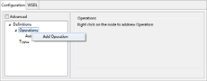
In Advanced (disabled) view, an operation can be added by selecting the option Add Operation from the context menu of the Operations node.
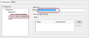
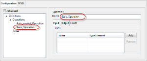
When an operation is added, the port type, binding, binding operation, Input, and Output messages will be automatically created in the format Auto_Created_Operation<n> which can be edited with your preferred name. On deleting the operation, all corresponding elements which are no longer referenced will be deleted based on the input from the user.
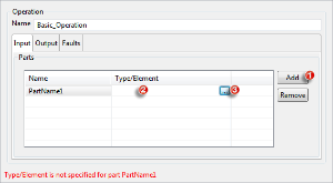
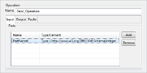
Figure 7: Operation configuration steps
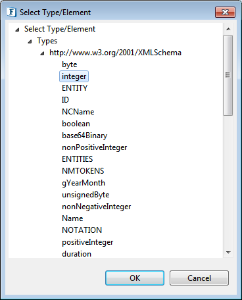
The input and output (and faults if necessary) name can be added by clicking Add button and then the Type/Element can be specified by clicking the cell under the column and then by clicking the ellipsis  button that appears.
Figure 8: Type/Element Selection steps
The tree shows the types and elements present in the schemas and their imports as shown in figure 7. The types are shown as children of Types node and any elements present will be shown under the Elements node. The table cell corresponding to the types dialog is editable and is populated as follows.
When a type or element is selected, the cell will be populated with QName of the element/type prefixed by "Type :" or "Element :" respectively.
Advanced enabled (check box selected)
This view is recommended only if you have a fair understanding of the creation of WSDL. In this view, it is possible to configure all the elements of the WSDL. The tree in the Advanced view shows a much detailed view of the elements of the WSDL. The configuration of a particular element can be done by selecting the node which shows the corresponding panel in the right side pane.
Definitions
This is the same as explained in the above section.
Types
This is the same as explained in the above section.
Apart from Types, you have the below attributes in Advanced enabled view:
- Bindings
- Messages
- Port Types
- Services
Each attribute is explained in the below sections.
Message
The messages for the web service can be added by selecting the option Add Message from the context menu which appears on right-clicking the Messages node. This will add the Message node as a child node of Messages. On selecting the added node, the panel as shown in the below figure is displayed in the right side pane.
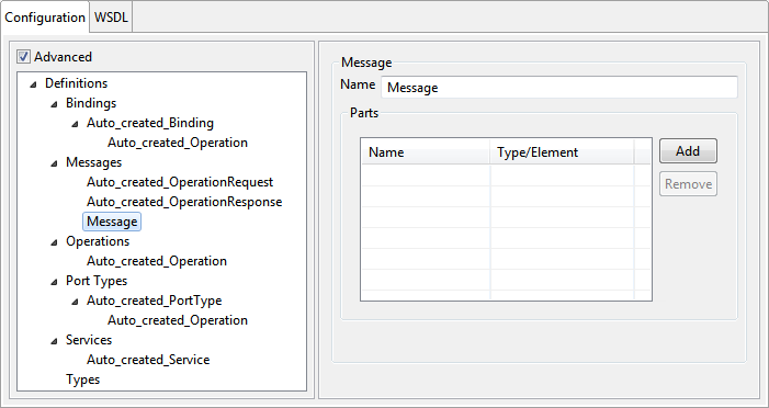
Figure 9: Message Configuration
Name
The name attribute of the message can be specified here. It provides a unique name among all messages defined within the enclosing WSDL document.
Parts
Messages consist of one or more logical parts. Each part is associated with a type from some type system using a message-typing attribute. Parts for the message can be added by using the add button in the table. The type/element for the part can be selected using the types dialog shown in Figure 7.
Port Type
The port types for the web service can be added by selecting the option Add Port type from the context menu which appears on right-clicking on the Port Types node. This will add a port type node as a child node of the Port Types node. On selecting the added node, the panel as shown in the below figure is displayed in the right side pane.
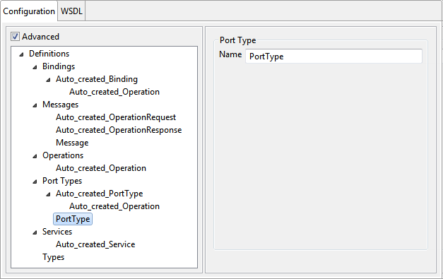
Figure 10: Port Type configuration
Name
The name attribute of the port type can be specified here. It provides a unique name among all port types defined within the enclosing WSDL document.
Operations
Operations can be added to a port by selecting the option Add Operation from the context menu which appears on right-clicking on the added port type node.
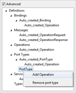
Figure 11: Adding Operation
This will add an operation node as a child node of the added port type node. On selecting the added node, the panel as shown in the below figure gets displayed in the right side pane.
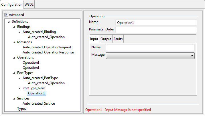
Figure 12: Advanced Operation Configuration
Name
The name attribute of the operation can be specified here. This need not be unique among the operations defined.
Parameter order
For RPC bindings, the parameter order can be specified using this field.
The value is a list of message part names separated by a single space. It MUST follow the following rules:
- The part name order reflects the order of the parameters in the RPC signature
- The return value part is not present in the list
- If a part name appears in both the input and output message, it is an In/Out parameter.
- If a part name appears in only the input message, it is an In parameter.
- If a part name appears in only the output message, it is an Out parameter.
Input tab
Name
The name of the input can be specified using this field. This name along with operation name and operation's output name uniquely identifies an operation within the enclosing port type.
Message
An input message can be selected from the combo box. It is recommended that the messages are added prior to configuring the operation.
Output tab
Name
The name of the output can be specified using this field. This name along with operation name and operation's input name uniquely identifies an operation within the enclosing port type.
Message
Output message can be selected from the combo box. It is recommended that the messages are added prior to configuring the operation.
Faults tab
Multiple faults can be added by using the table under the Faults tab. The message corresponding to the fault can be selected from the drop-down.

Figure 13: Adding faults to operation
Bindings
The bindings for the web service can be added by selecting the option Add Binding from the context menu (right-click the Bindings node). This will add a binding node as a child node of the Bindings node. Select the added node to view the details on the right side pane.
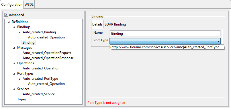
Figure 14: Binding configuration
Name
The name attribute of the binding can be specified here. It provides a unique name among all bindings defined within the enclosing WSDL document.
Port Type
The port type corresponding to this binding can be selected from the drop-down list.
SOAP Binding

Figure 15: SOAP Binding configuration for binding
The SOAP binding information of the binding can be specified by selecting the tab SOAP binding as shown in Figure 14.
Transport
The value of the required transport attribute indicates which transport of SOAP this binding corresponds to.
Style
The value of the style attribute is the default for the style attribute for each contained operation.
Binding Operations
Binding operations can be added to a port by selecting the option Add Binding Operation from the context menu which appears on right-clicking on the added binding node as shown in figure 15
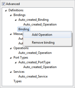
Figure 16: Adding binding operation
This will add binding operation node as a child node of the added binding node. On selecting the added node, the panel as shown in figure 16 is displayed in the right side pane
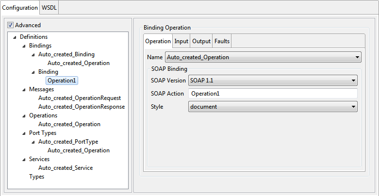
Figure 17: Binding operation configuration
The various details of binding operation can be specified by selecting the tabs as explained below.
Binding Configuration
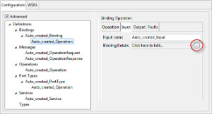
Go to Input/Output tab and click the button against Binding Details property to configure the binding details.
Figure 18: Navigating to Binding Configuration
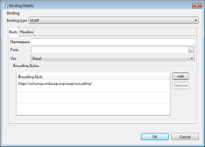
Binding type
Select the type of binding to be used. It can either be simple SOAP or Mime MultiPartRelated. To send or receive attachments, select Binding type as Mime MultiPartRelated.
SOAP Binding
Body and Header information can be configured for SOAP Binding type as seen in the Binding Details image in the figure above.
Body Tab
This tab can be used to configure the attributes of the soap:body element.
Namespace
This can be used to specify the namespace corresponding to the SOAP body. This namespace should not be present in the namespaces defined in the definitions panel.
Parts
The optional parts attribute indicates which parts appear somewhere within the SOAP Body portion of the message. If the parts attribute is omitted, then all parts defined by the message are assumed to be included in the SOAP Body portion.
Use
The use attribute indicates whether the message parts are encoded using some encoding rules, or whether the parts define the concrete schema of the message.
Encoding Styles
The value of the encodingStyle attribute is a list of URIs. The URIs can be added using the table as shown in Figure 17. The URI represents encodings used within the message, in order from most restrictive to least restrictive.
Use
Headers Tab
SOAP header corresponding to the input/output can be specified by adding them to the table by clicking the Add button under the Headers tab.
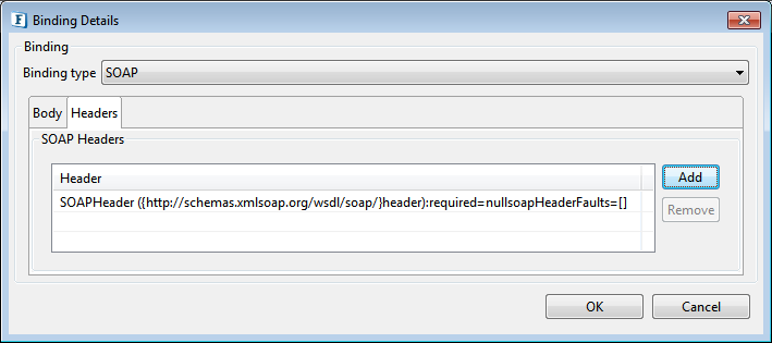
Figure 19: Adding SOAP Headers
The SOAP Headers can be configured by clicking on the ellipsis  button which appears when you click the Header name.
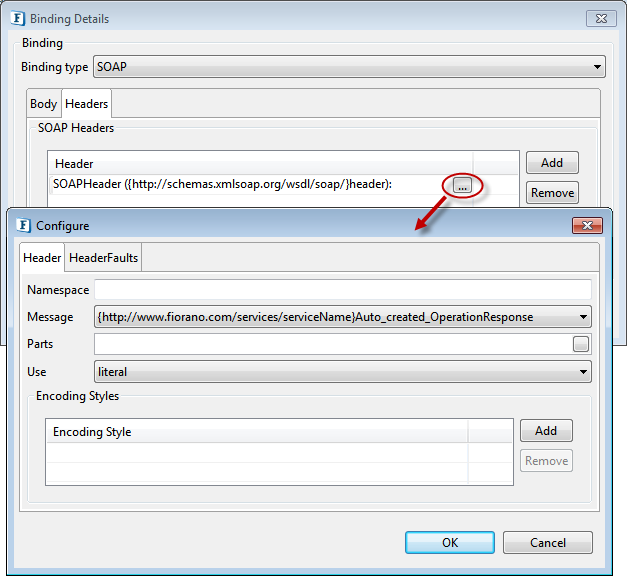
Figure 20: SOAP Header configuration
Namespace
This can be used to specify the namespace corresponding to the SOAP body. This namespace should not be present in the namespaces defined in the definitions panel.
Message
The message and the part reference the message part that defines the header type. The referenced message need not be the same as the message that defines the SOAP Body.
Part
The message and the part reference the message part that defines the header type. The schema referenced by the part MAY include definitions for the soap:actor and soap:mustUnderstand attributes if use="literal", but MUST NOT if use="encoded".
Use
The use attribute indicates whether the message part is encoded using some encoding rules, or whether the part defines the concrete schema of the message.
Encoding Styles
The value of the encodingStyle attribute is a list of URIs. The URIs can be added using the table as shown in Figure 19. The URI represents encodings used within the message, in order from most restrictive to least restrictive
Header Faults
The Header faults corresponding to a header can be defined by selecting the tab header Fault and adding an entry in the table SOAP Header Faults table. The SOAP Header fault can be configured by clicking on the ellipsis as shown in Figure 20.
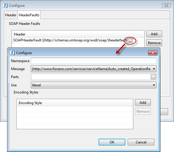
Figure 21: SOAP Header fault configuration
The header fault elements allow specification of the header type(s) that are used to transmit error information pertaining to the header defined by the soap:header. The attributes namespace, message, part, use and encoding styles are similar to those defined for SOAP Header.
MIME MultiPartRelated Binding
The following binding information can be configured here when Binding type is chosen as MIME MultiPartRelated.
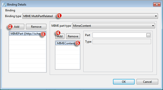
Figure 22: MIME MultiPartRelated Binding configuration
MimeContent
MIME Contents can be added using the add button. Corresponding Part and Type of the MIME content can be configured.
Part
Select the corresponding Part.
Type
Type specifies the content type of this particular mime part as image/jpeg, text/*.
SOAP
This is the same as the SOAP Binding configuration explained above.
Operation tab
Name
The name of the operation to which this binding operation corresponds can be selected from the drop-down.
SOAP Binding
This information corresponds to the attributes for the soap:operation element that will be added to the binding operation element.
SOAP Action
The soapAction attribute specifies the value of the SOAPAction header for this operation.
Style
The style attribute indicates whether the operation is RPC-oriented (messages containing parameters and return values) or document-oriented (the message containing document(s))
Input tab
The input tab can be used to specify the binding input information.
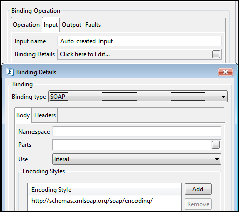
Figure 23: Binding input Configuration
Input name
The name of the input for the binding operation can be specified here. This along with operation name and the output name uniquely identifies the operation to which the binding operation corresponds to.
Binding
Binding Configuration explains binding configuration.
Output tab
The output tab can be used to specify the binding output information as shown in figure 23.
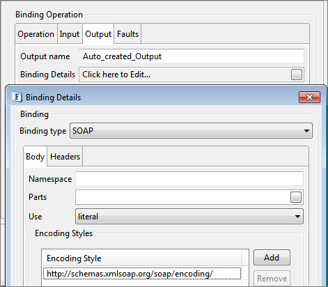
Figure 24: Binding Output configuration
Output name
The name of the output for the binding operation can be specified here. This along with operation name and the input name uniquely identifies the operation to which the binding operation corresponds to.
SOAP Binding
The SOAP binding information for the binding output can be configured similarly as explained in the Binding input in the previous sections.
Faults tab
The binding information for faults can be defined by adding an entry in the table and clicking on the ellipsis ![]() which opens a dialog box
which opens a dialog box
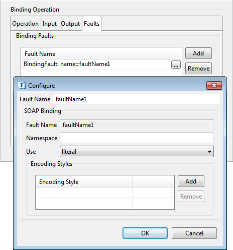
Figure 25: Faults configuration
Fault Name
The name attribute of the fault element can be specified here.
SOAP Binding
Fault Name
The name attribute for soap:fault element. This is not editable and is the same as the fault name.
Namespace
This can be used to specify the namespace corresponding to the SOAP body. This namespace should not be present in the namespaces defined in the definitions panel.
Use
The use attribute indicates whether the message parts are encoded using some encoding rules, or whether the parts define the concrete schema of the message.
Encoding Styles
The value of the encodingStyle attribute is a list of URIs. The URIs can be added using the table as shown in figure 22. The URI represents encodings used within the message, in order from most restrictive to least restrictive.
Services
The service for the web service can be added by selecting the option Add Service from the context menu which appears on right-clicking on the Services node. This will add a service node as a child node of the services node. On selecting the added node, the panel as shown in figure 23 is displayed in the right side pane. Only one service per instance is supported presently.

Figure 26: Service and ports configuration
Name
The name of the service can be specified here. The service name must be unique for WSStub instances configured on the same peer server.
Ports
A port defines an individual endpoint by specifying a single address for a binding.
Name
The name attribute of the port can be specified here. It provides a unique name among all ports defined within the enclosing WSDL document.
Binding
The binding corresponding to port can be specified from the combo box.
SOAP Address
The SOAP address binding is used to give a port an address (a URI). The URI scheme specified for the address must correspond to the transport specified by the soap:binding.
WSDL
This is the XML form of the WSDL that is generated from the configuration done using Advanced views. If you are good at working with XML tags, you may edit the WSDL by enabling the Make WSDL editable check box.
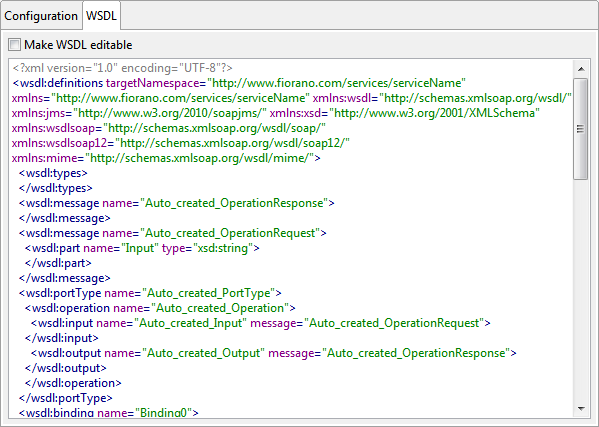
Figure 27: WSDL view
Errors Messages
Figure 28: Validation error
The validation for a particular panel is done when you try to navigate away from the tree node corresponding to the panel. Validation errors get notified at the lower-left part of the screen and the details in the particular panel, both marked in a red color font.
FES Connection Configuration
Click the button against FES Connection Configuration property to provide FES connection configuration.
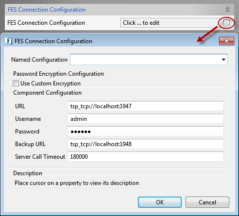
Figure 29: FES Connection configuration
FES URL
The URL of Enterprise Server to which the Peer Server on which the component is running is connected.
Username
The username that should be used to connect to the enterprise server.
Password
The password that should be used to connect to the enterprise server.
Server Call Timeout
Sets the timeout for the calls made to the Enterprise Server. By default, it is set to 180 Seconds. This value should be increased to avoid timeout with the Enterprise server while launching Components.
FES Backup URL
The alternate URL that should be tried for connecting to the Enterprise Server if the Enterprise Server cannot be connected to using the URL mentioned against property FESURL.
Execution Configuration

Figure 30: Execution configuration
Execution Timeout
WSStub component receives client request on its output port and sends the request message to the connected components. After the processing is completed by the connected components response message is sent to WSStub input port and from there it will be sent to the client.
WSStub component accepts the response if it reaches before the timeout period. If no response is received, on timeout Error message will be sent to the client saying No message received till the timeout period.
Message TTL
This value is set as Time to live property on the request message. The request message will be discarded after the timeout. 0 indicates infinite time.
Store Imported Schemas
Selecting this property enables to save schemas in the Schema Repository.
HTTP Authentication Configuration
To connect to RESTful service where the basic authentication is present, the HTTP authentication has to be configured in the component. Click the button against HTTP Authentication Configuration property to provide the configuration in the Editor dialog box.
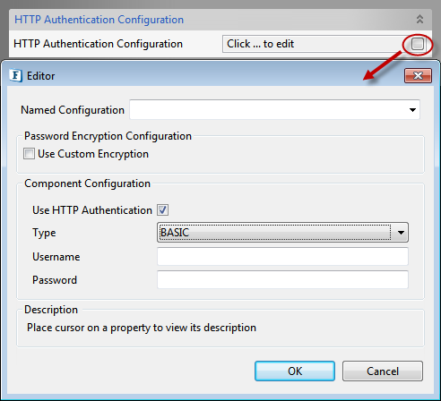
Figure 31: HTTP Authentication Configuration
Use HTTP Authentication
HTTP authentication support for the Web Services can be provided by selecting this property.
Type
The type of HTTP Authentication can be selected for the drop-down. At present only BASIC authentication is supported.
Username
Username to be used by the WSStub component while deploying the Web Service. The entry for this user name has to be present in Realm.properties file. If this user name is not present, the component will not launch.
Password
Password to be used by the WSStub component while deploying the Web Service. If this password is not present in Realm.properties file the component will not launch.
Using Basic Authentication
Before enabling this property in WSStub, basic authentication has to be enabled in FPS Jetty Server and in the bcwsgateway web application (FIORANO_HOME/esb/server/jetty/fps/webapps/bcwsgateway). Procedure to enable basic authentication in Jetty Server and in the web app is explained below.
Jetty Server
To enable Basic Authentication in Jetty Server, perform the following actions:
- Stop the FPS Server if it is running.
- Open FPS profile in Fiorano eStudio and navigate to FPS > Fiorano > Esb > Jetty > Jetty.
In the Properties of Jetty panel on the right, enable Basic Authentication (select the BasicAuthSupported check box) and provide the fully qualified path of Realm.properties file in the RealmProperties property.
- Save the profile.
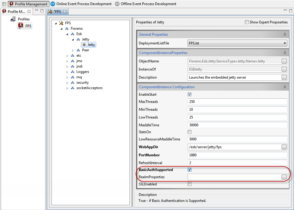
Figure 32: Enabling Basic Authentication in FPS Jetty server
Webapp
To enable Basic Authentication in webapp, perform the following actions:
- Open Web.xml file located at FIORANO_HOME/esb/server/jetty/fps/webapps/bcwsgateway/WEB-INF.
- Uncomment the security-constraint and login-config elements and save the file.
- Delete the Peer Server cached profile from FES runtime by deleting the folder FIORANO_HOME/runtimedata/EnterpriseServers/<Profile Name>/FES/peers/<peer profile>.
- Start the FPS server.
- The basic authentication is enabled in FPS Jetty Server, and in the web generated WSDL, the EndPoint Host and Port are seen under the wsdl:service element.
Now the authentication can be enabled in WSStub by enabling Use HTTP Authentication property and then provide the credentials (set of username and password) present in Realm.properties file.
UserName
Username to be used by the WSStub component while deploying the Web Service. The entry for this user name has to be present in Realm.properties file. If this user name is not present, the component will not launch.
Password
Password to be used by the WSStub component while deploying the Web Service. If this password is not present in Realm.properties file the component will not launch.
Realms
Security realms allow securing the web applications against unauthorized access. Protection is based on authentication (identifying who is requesting access to the webapp) and access control (restricting what can be accessed and how it is accessed within the webapp).
A webapp statically declares its security requirements in the web.xml file. Authentication is controlled by the <login-config> element. Access controls are specified by <security-constraint> and <security-role-ref> elements. When a request is received, the web container checks if the user performing the request is authenticated and if the user has a role assignment that permits access to the requested resource. Access to the resource is allowed only when the user is authorized and has the required permissions.
A realm has a unique name and is composed of a set of users. Each user has authentication information (Example: a password) and a set of roles associated.
More than one realm can be configured depending on the needs.
Fiorano uses a simple realm whose authentication and authorization information is stored in a properties file. Each line in the file contains a username, a password, and 0 (zero) or more role assignments. The format is:username: password[,rolename ...]
where:
- username is the user's unique identity
- password is the user's password
- rolename is the user's role
Sample content of Realm.properties file is shown below:
- admin: admin,admin
- user: password,user
- guest: guest,read-only
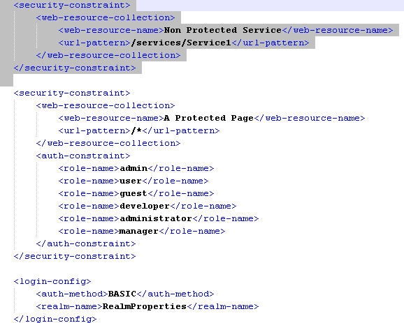
In order to disable the basic HTTP authentication for some specific services, you need to edit the web.xml file. In the following example, if you choose to disable the basic authentication for Service1, then add security-constraint element to the web.xml as specified in the below figure.
JMS Settings

Figure 33: JMS Settings
Enable JMS Transport
SOAP over JMS
This property enables SOAP over JMS, which can be configured by providing the attributes below that gets editable.
JNDI Configuration
Click the button against JNDI Configuration property to provide the configuration in the dialog box.
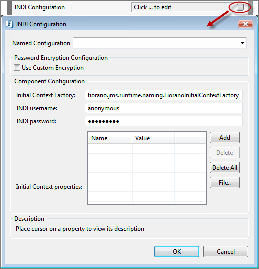
Figure 34: JNDI Configuration
Component Configurations
Initial Context Factory
If JMS Transport is enabled, jndiInitialContextFactory parameter is appended to endpointURI
JNDI Username
Enter JNDI username
JNDI Password
Enter JNDI password
Initial Context Properties
Context properties are appended to the endpointURI. The 'jndi-' prefix is appended to property names.
Connection Configuration
Click the button against the Connection Configuration property to provide the configuration in the dialog box.
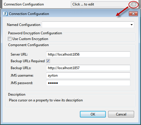
Figure 35: Connection Configuration
Component Configuration
Server URL
Enter JMS provider URL
Backup URLs Required
Check if backup URLs are required.
Backup URLs
BackupURLs entered are appended to the endpointURL as parameter named 'jndi-BackupConnectURLs'
JMS Username
Enter JMS username.
JMS Password
Enter JMS password.
Destination Type
The JMS type of the destination. Select one of these destination types:
- Topic: This value is selected when the type of destination is 'Topic'.
- Queue: This value is selected when the type of destination is 'Queue'.

Figure 36: Destination types
Provide the destination type that should be used for listening to request and send a response to, based on the service name configured under WSDL Configuration. For example, if ServiceName is 'Test', then "Test" & "Test__REPLY_TO" destinations of type mentioned here are created.
WS-Security Configuration
WS-Security
This property is used to define WS Standards like WS-Addressing, WS-Reliable Messaging, and WS-Security.
Request WS-Security
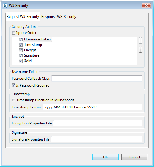
Figure 37: WS Request Security
Security actions
The different actions are as below and the properties to be set for using them are explained in the below sections:
- Username Token
- Timestamp
- Encrypt
- Signature
- SAML
The order of the actions can be altered by clicking the tabs on the right side of the option. To enable an action/security function, the checkbox against it must be selected.
Ignore Order
If this property is enabled, the order of Security actions will be ignored for the incoming request. If disabled, the order of a security function determines when this function will be applied when multiple security functions are being used.
Username Token
Determines whether the server should perform Username token identification or not.
Password Callback Class
This is needed by the security functions to get the password and to verify the username/password pair. The password callback class should implement javax.security.auth.callback.CallbackHandler class. This Password Callback class should be the fully qualified name of the class. The jar which contains the password callback class must be placed in '%FIORANO_HOME%\esb\server\jetty\fps\webapps\bcwsgateway\WEB-INF\lib'.
Is Password Required
This property should set to false if the Username security token is used without a password. No need to provide Password callback class if this property is set to no.
Timestamp
Determines whether the soap request has a timestamp in security header or not. In this case, the message is valid for 5 minutes or 300 seconds after the creation of the message.
Timestamp Precision in MilliSeconds
If this is set, timestamps will have precision in milliseconds. Otherwise, it will be seconds.
Encrypt
Determines whether the soap request (or some parts of it) is encrypted or not.
Encryption Properties File
The name of the crypto property file to use for decryption of the soap request. If this parameter is not specified and if both the "Signature Properties filename" and "Signature" are set to yes, then the decryption function uses signature property file, else the handler throws an AxisFault. The properties file must be placed in '%FIORANO_HOME%\esb\server\jetty\fps\webapps\bcwsgateway\WEB-INF\classes'
Description for each property in the sample above:
- org.apache.ws.security.crypto.provider: Implementation class for the security provider. Fiorano internally uses bouncycastle, to use the same this property must be set to "org.apache.ws.security.components.crypto.Merlin". To use other providers, the provider jar must be placed in '%FIORANO_HOME%\esb\server\jetty\fps\webapps\bcwsgateway\WEB-INF\lib' and the fully qualified name of the appropriate provider class has to be set for this property.
- org.apache.ws.security.crypto.merlin.file: The path to the keystore file.
- org.apache.ws.security.crypto.merlin.keystore.type: The keystore type, for example, JKS for the Java key store. Other keystore types, such as pkcs12 are also possible but depends on the actual Crypto implementation.
- org.apache.ws.security.crypto.merlin.keystore.password: The password to read the keystore. If this property is not set, then the pwcallbackproperty must be defined.
- org.apache.ws.security.crypto.merlin.keystore.alias: The alias name under which the private key/certificate stored in keystore
- org.apache.ws.security.crypto.merlin.alias.password: Password for private key/certificate inside keystore stored under given alias (not used for encryption)
Signature
Determines whether the soap request (or some parts of it) is signed or not.
Signature Properties File
The name of the crypto property file to use for SOAP Signature. Please see the description of "Encryption Properties filename" for the details of the properties file.
SAML
SAML property under Security Actions determines whether the server should perform SAML Token identification for the incoming request or not.
Response WS-Security
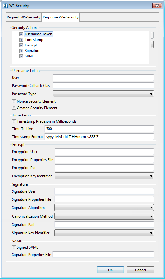
Figure 38: WS Response security
Security Actions
Refer the respective section under Request WS-Security as the properties and option available to alter the order are the same.
Username Token
Determines whether the server should perform Username Token Identification on response or not. If this property is set, the response from the server contains Username and Password security headers.
User
This property is used as the username for the UsernameToken security function. It is also used as the alias name in the keystore to get user's certificate or private key to perform signing for the Signature security function. It is also used as the fallback for the encryption security function in case of "Encryption User" is not specified and "Encryption" in response is enabled.
Password Callback Class
This is needed by the security functions to get the password and to verify the username/password pair. The password callback class should implement javax.security.auth.callback.CallbackHandler class. This Password Callback class should be the fully qualified name of the class. The jar which contains the password callback class must be placed in '%FIORANO_HOME%\esb\server\jetty\fps\webapps\bcwsgateway\WEB-INF\lib'.
Password Type
The Password type specifies how the server sends the password value to the client.
PasswordText
Password is sent in raw text format within the security header of the soap response.
PasswordDigest
Password is sent in digest format within the security header of the soap response.
PasswordNone
No password will be sent in the security header. This option is useful when the user wants to specify the username without any password.
Nonce Security Element
Specifies whether to use nonce element in the security header or not. When UsernameToken security function is used, then nonce security element can be employed to prevent message replay attacks. A nonce is a random value that the client creates to include in each UsernameToken that it sends. Although using a nonce is an effective countermeasure against replay attacks, it requires the server to maintain a cache of used nonce's, consuming server resources.
Created Security Element
Specifies whether to use Created element in the security header or not. This element denotes the time of creation of a nonce. Combining a nonce with a creation timestamp has the advantage of allowing a server to limit the cache of nonce's to a "freshness" time period, establishing an upper bound on resource requirements.
Timestamp
Specifies whether the soap response from the server should contain timestamp header or not.
Timestamp Precision in MilliSeconds
If this is set, timestamps will have precision in milliseconds. Otherwise, it will be seconds.
Time To Live
The time difference between creation and expiry time in the WSS Timestamp. This should be specified in seconds.
Encrypt
Determines whether the server should encrypt the soap response (or some parts of it) or not.
Encryption User
Username for the encryption function. The encryption function uses the public key of this user's certificate. If this parameter is not set, then the encryption function falls back to the "User" parameter to get the certificate. The encrypt function will not authenticate the user. So there is no need to set any password call back class for encrypt.
Encryption Properties File
The name of the crypto property file to use for SOAP Encryption in response. If this parameter is not specified and if both "Signature Properties filename" and "Signature" in response are set, then the encryption function uses the signature property file. Otherwise, the handler throws an AxisFault. The properties file must be placed in '%FIORANO_HOME%\esb\server\jetty\fps\webapps\bcwsgateway\WEB-INF\classes'. Please see the description of "Encryption Properties filename" in request security for the details of the crypto properties file.
Encryption Parts
This parameter specifies which parts of the response shall be encrypted. The value of this parameter is a list of semi-colon separated element names that identify the elements to encrypt. An encryption mode specifies and a namespace identification, each inside a pair of curly brackets, may precede each element name. The encryption mode is either {Content} or {Element}. 'Element' encryption mode will encrypt the entire element including start and end tags. 'Content' encrypt mode will encrypt only the content of the specified element. The default encryption mode is 'Content'.
For example, if we set "{Element}{http://example.org/paymentv2\}CreditCard;{}{}UserName" list to this property, then the first entry of the list identifies the element CreditCard in the namespace http://example.org/paymentv2, and will encrypt the entire element. In the second entry, the encryption modifier and the namespace identifier are omitted. In this case, the encryption mode defaults to Content and the namespace is set to the SOAP namespace.
The element name, the namespace identifier, and the encryption modifier are case sensitive. To specify an element without a namespace use the string Null as the namespace name (this is a case-sensitive string). If no list is specified, the handler encrypts the SOAP Body in Content mode by default.
Encryption Key Identifier
Select the key identifier type to use.
DirectReference
The security function takes the signing certificate, converts it to a BinarySecurityToken, puts it in the security header. Thus the whole signing certificate is transferred.
X509KeyIdentifier
The encryption method uses the public key associated with this certificate to encrypt the symmetric key used to encrypt data. The certificate is converted into a KeyIdentifier token and sent to the server. Thus the complete certificate data is transferred.
SKIKeyIdentifier
The security function uses SKIKeyIdentifier.
IssuerSerial
The encryption method uses the public key associated with this certificate to encrypt the symmetric key used to encrypt data. The issuer name and the serial number of the signing certificate are sent to the server.
Signature
Determines whether the soap response (or some parts of it) should be signed or not.
Signature User
This name is used as the alias name in the keystore to get user's certificate and private key to perform signing. If this parameter is not set, then the signature function falls back to the "User" parameter to get the certificate. Password for the user to get certificates from the keystore should be provided in the Password Callback class.
Signature Properties File
The name of the crypto property file to use for SOAP Signature. Please see the description of "Encryption Properties filename" for the details of the properties file.
Signature Parts
The parameter specifies which parts of the request shall be signed. Please see the description of "Encryption Parts" for the syntax.
Signature Key Identifier
Select the key identifier type to use. Please see the description of "Encryption Key Identifier" for the descriptions of key identifiers.
Signature Algorithm
The parameter specifies signature algorithm to be used. If an algorithm is not specified, then the algorithm "http://www.w3.org/2000/09/xmldsig#rsa-sha1" will be used by default.
Canonicalization Method
The parameter specifies the canonicalization method to be used in the process of signing the request. If no method is specified then the method "http://www.w3.org/2001/10/xml-exc-c14n#" will be used by default.
SAML
Determines whether the server should perform SAML Token Identification or not.
Signed SAML
Specifies whether to use signed SAML or unsigned SAML. If Signed SAML is used, then the server performs two actions inserting a SAML Token (unsigned) and an associated Signature. So define both the actions SAML Unsigned and Signature at client side to resolve these security headers. If Signed SAML is used, the signature properties should be specified in this panel without selecting the property "Signature WS-Security".
SAML Properties File
The name of the SAML properties file. This file must be placed in '%FIORANO_HOME%\esb\server\jetty\fps\webapps\bcwsgateway\WEB-INF\lib'.
SSL Configuration
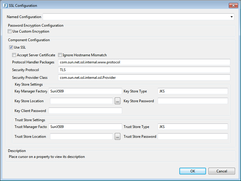
Figure 39: SSL Configuration
Please refer the SSL Configuration section in JMSIn5.0 page.
Miscellaneous Configuration
This panel comprises of the tabs Attachments Configuration, Additional Configuration, and Encrypt/Decrypt Configuration to set up the respective configuration.
Attachments Configuration
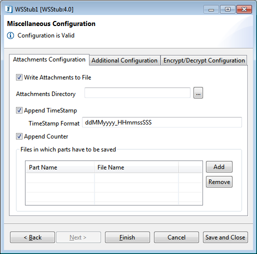
Figure 40: Attachments Configuration
Write Attachments to File
Select this option to write attachments to file, if not selected attachments will be sent to the output port. While sending to the output port, Attachments will be base64 encoded if they do not contain text content.
As you enable this property, the below attributes turn editable; provide the details accordingly.
Attachments Directory
Provide the path of the Directory in which attachments needs to be saved.
Append TimeStamp
Select this option to append a timestamp to the file name while writing attachments to file.
TimeStamp Format
Specify the timestamp format to be appended to the file name.
Append Counter
Select this option to append a counter to the file name in case a file with the same name exists. If Is Append TimeStamp is also enabled then timestamp will be appended before appending counter.Ex: fileName_0 (without timestamp), fileName_1313406444699_1 (with timestamp).
Files in which parts have to be saved
This table will be updated automatically with the mime parts present in the WSDL. By default file name will be generated same as that of part name and can be changed if required.
Part Name
The unique name of the part in the message. A unique name will be generated by appending ____ to the partname. For example, if the part Part1 in the opeartion Operation1 is a mime part, then the key populated in this table will be SOAP11_Operation1Part1 for SOAP1.1, SOAP12Operation_Part2 for SOAP1.2. If a WSDL does not contain any defined mime parts and webservice need to save the attachments, then the user should configure the table manually. .
File Name
Specify the file name in which the corresponding part message needs to be saved.
Additional Configuration
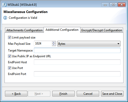
Figure 41: Additional Configuration
Limit payload size
Enable this checkbox to limit the payload size in the server. If the request size is more than configured payload size then server throws soap fault saying soap message size is exceeded.
Max Payload Size
This property specifies the maximum payload size. If the client's request exceeds this value, the server sends a soap fault, if Limit Payload Size is selected.
Target Namespace
A non-empty value in this field is set to target namespace for Request/Response schemas.
For example, if the namespace is 'http://www.test.com', corresponding namespaces for Request/Response schemas are 'http://www.test.com/OperationName/Input' and 'http://www.test.com/OperationName/Output' respectively.
Use Public IP as EndPoint URL
Enable this option to use different EndPoint for the web service. Provide the EndPoint Host and EndPoint Port
EndPoint Host
Provide the Host name.
Use Port
If you want to provide a different port other than default port value: 1880, enable this property.
EndPoint Port
Provide the port number.
In the generated WSDL, the EndPoint Host and Port are seen under the wsdl:service element.
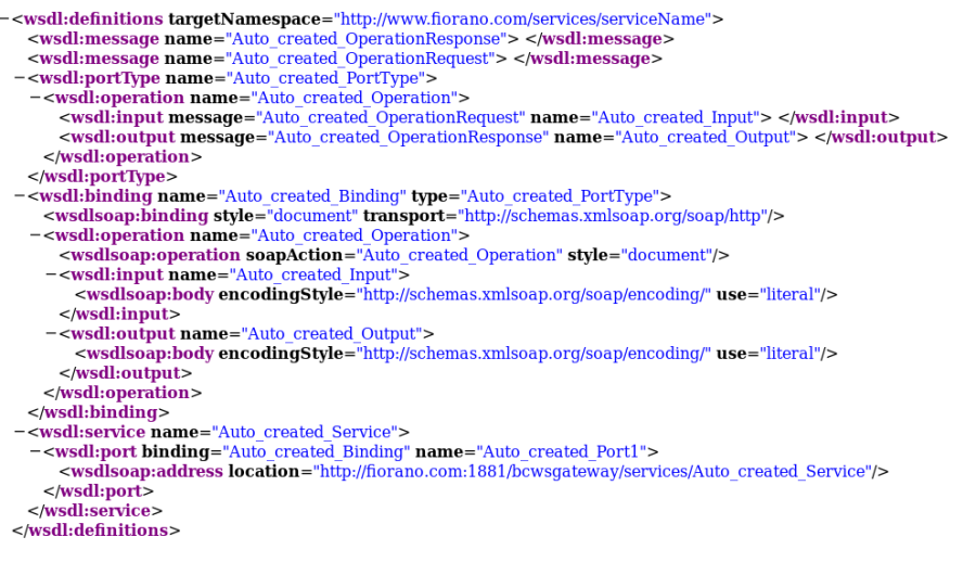
Figure 42: WSDL generated
Sending/Receiving attachments
To receive attachments under advanced section of WSDL configuration, navigate to Auto_created_OperationRequest message and then click Add.
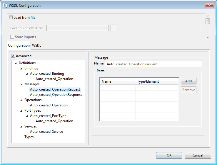
Figure 43: WSDL Configuration with Response Elements defined
To send an attachment, select Auto_created_OperationResponse and then click Add.
Attachments are of MIME parts. To configure a request element as MIME, select the Auto_created_Operation under Auto_created_Binding in the Bindings section.
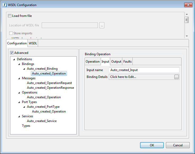
Figure 44: Configuring Bindings
To receive attachments or send attachments or both, configure bindings under Input tab or Output tab of the right pane or both respectively (refer MIME MultiPartRelated Binding subsection under Bindings section).
In the Binding type drop-down box available at the top of the window, select the option MIME MultiPartRelated. Add a MIMEPart by clicking the Add button in the left panel.

Figure 45: Binding Details Window
Configure this MIMEPart to bind to one of our request elements; click on the added MIMEPart which opens the inner pane. In the inner pane, click the Add button to configure a MimeContent. Then click on the added MimeContent cell to bind it to one of the request elements/parts.
In the property Part, select Input in case of a request, select Output in case of response.
If an attachment is to be received into a file, select the "Write attachment to File" property in the Miscellaneous Configuration of the CPS.
Encrypt/Decrypt Configuration
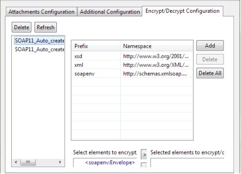
Figure 46: Encrypt/Decrypt Configuration
For Encrypt/Decrypt configuration refer Encrypt Decrypt Configuration section under Common Configurations.
Port Generation
The ports will be generated based on the configuration of WSDefinition as follows:
- For each operation which has SOAP binding defined request, response and error ports will be generated.
- The name of the ports will be prefixed by the type of SOAP binding i.e., SOAP11 or SOAP12.
The prefix is followed by <operation name> and the type of port.
Example
For an operation with name operationName and SOAP11 binding, ports with following names will be generated
- Output port with name SOAP11_operationName_REQUEST
- Input port with name SOAP11_operationName_RESPONSE
- Input port with name SOAP11_operationName_FAILURE
Port Schema Structures
Request Schema
The following figure shows the sample request schema when the Binding type is 'MIME MultiPartRelated'. The mime parts will be present in the Attachments element as specified in the below figure.
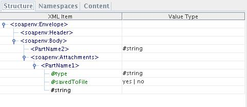
Figure 47: Request Schema
Type
Type specifies the Content type of the attachment.
SavedToFile
Whether the attachment was saved to file or not. If yes, the attachment part element contains the file path to which it got saved else the entire attachment otherwise it contains the attachment content. Attachment part content will be base64 encoded if the attachment contains an image or a binary content.
Response Schema
The following figure shows the response schema elements when the Binding type is 'MIME MultiPartRelated'.

Figure 48: Response Schema
Type
The content type of the attachment.
IsURL
Specifies whether the attachment is an URL or not. If yes, attachment part element contains the URL of the attachment, otherwise the attachment content.
Functional Demonstration
Scenario 1
Below figure and adjoining explanation demonstrates how WSStub can be used to deploy the Event Process as Web Service.

Figure 49: Scenario demonstration
In the flow, WSStub is connected to an SMTP component. WSStub component sends the client requests to SMTP and gets the SMTP response which is sent back to the client. An operation is added in basic view and its input part type is set as root element of SMTP component's input port schema, output part type is set as root element of SMTP component's output port schema and a fault part is added and its part type is set as root element of error port schema of SMTP component.
When the Event Process is launched, it gets deployed as Web Service with service name and added operation name specified in the CPS. On right-clicking and selecting view wsdl, the user can view the WSDL for this WSStub in a web browser.
A WebserviceConsumer component can be configured to invoke this Web Service by providing the URL of this wsdl (in the Managed Connection Factory panel of WS consumer's CPS) and by selecting the Web Service Operation (In Interaction Configuration Panel).
Sample request and response to WebserviceConsumer component which accesses the deployed Web Service is shown below.
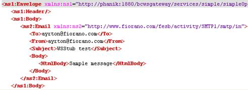
Figure 50: Sample Request

Figure 51: Sample Response
Scenario 2
Configure Response WS-Security with values as in the below figure and check the response.
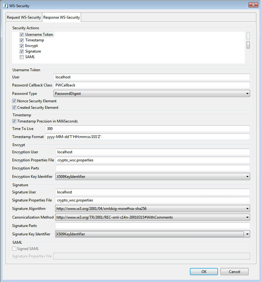
Figure 52: Sample WS-Security - Response configuration
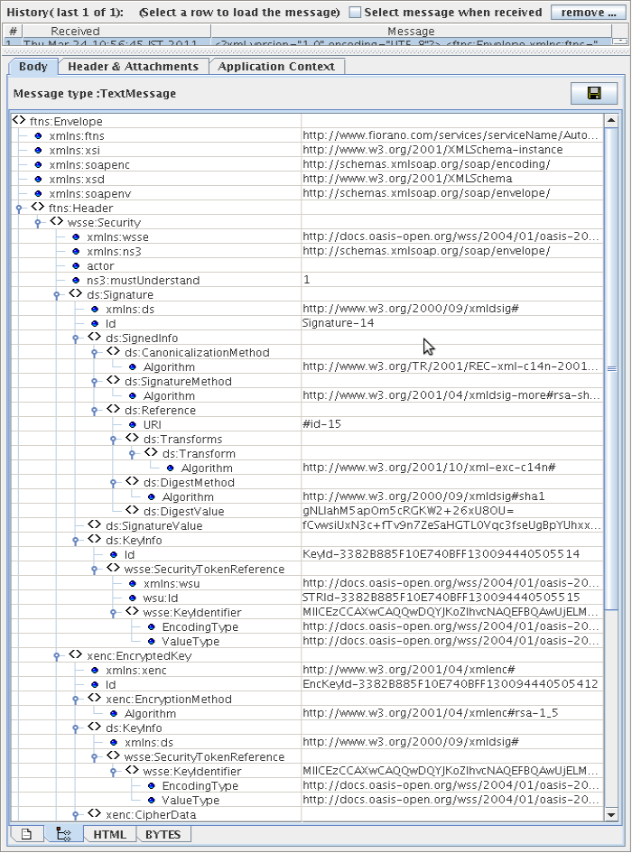
Figure 53: Sample Output in the case of the above configuration
Useful Tips
- Destinations created when JMS Transport is enabled can only be deleted manually. Using the Connection Management perspective, a user can manage destinations.
- Charset property for the response message (other than the system charset) can be provided using 'Charset' message property.
- For SSL to work properly the JDK version used should be greater than 1.5.0_08 and the jars present in JDK_HOME/jre/lib/ext should be copied to $FIORANO_HOME/esb/lib/ext.
- When WSStub component is configured to launch on HA (High Availability) Peer Servers
- If both Primary and Secondary Servers are on the same machine
Initially, if WSStub is launched on the Primary Server, the generated WSDL URL contains Primary Server's jetty port number. In case of Primary Server failover, the Secondary Server becomes Active and relaunches the component. WSDL will be regenerated and if the Secondary Server uses a different jetty port then the WSDL URL is changed. The clients have to be reconfigured to use a new URL in this case.
To avoid this situation, it is recommended to use the same jetty ports for both Primary and Secondary Peer Servers.
Jetty service will be started only after the server is started successfully. In case of HA, only one server will be active at a given time and the Jetty Server will be running only in the active server and there will be no bind exceptions even if both the servers use the same port number for Jetty. - If both Primary and Secondary servers are on different machines
In this case, if the failover happens the hostname/IP address in the WSDL URL will be changed. So the clients have to be reconfigured accordingly.
HTTP headers are received from the gateway as message properties with the header name prefixed with http_. For example, http_Content-Type. - The service name must be unique for WSStub instances configured on the same peer server.
- If both Primary and Secondary Servers are on the same machine
- Sending Empty HTTP Response with 202 Status Code: WSStub Component can be used for an asynchronous request pattern where an HTTP Response with status code 202 and empty content is returned to inform the client that their invocation has been received. To achieve this, we need to send a JMS message to the response port of the WSStub with the string property http_statusCode set to 202.
- Enabling SOAP Compression in WSStub:
- Open Web.xml file located at FIORANO_HOME/esb/server/jetty/fps/webapps/bcwsgateway/WEB-INF.
- Uncomment the filter and filter-mapping elements and save the file.
- Copy the jars present at FIORANO_HOME/extlib/soapCompression to FIORANO_HOME/esb/server/jetty/fps/webapps/bcwsgateway/WEB-INF/lib.
- Delete the Peer Server cached profile from FES runtime by deleting the folder FIORANO_HOME/runtimedata/EnterpriseServers/<Profile Name>/FES/peers/<peer profile>.
- Start the FPS server.
- WSStub instances that are configured previously can be used as they were without opening the CPS. However, if the WSStub instance is reconfigured then there will be the following changes:
- Port names are changed
This would result in the routes leading to and from the component to disappear on closing the CPS. - Schemas on ports are changed
This would mean that the already defined transformations are no longer valid and will have to be redefined.
So it is recommended to save the transformations defined on the route externally and redefine the transformations after the component is configured. - Web Service name changed
The webservice name will be the context name appended with the suffix "Service" for the old WSStub components. If we deploy the same WSStub without any configuration changes, then the web service name will be context name itself. No suffix will be appended. This will result to reconfigure the Web service consumer components configured to use this service should be reconfigured to fetch the service name.
- Port names are changed
Whenever axis fault is thrown as in the case of username token authentication, the hostname is also included in the detail as shown below:
For security reasons, it is ideal to remove hostname from Axis fault. To remove the hostname, set the system property "REMOVE_HOSTNAME_IN_FAULT" to true in either of the peer server configuration files below:
- server.conf: $Fiorano_Home\esb\server\bin
- fps.conf file: $Fiorano_Home\esb\fps\bin
