Common Components Configurations
Components with implicitly defined JMS messaging properties
This chapter describes the configurations that are common across a most of adapters. However, if there are any additional component specific details for any of the configurations which are not described here, such details can be found in that component help file.
Component instance properties appear in the Properties pane when a component instance of an application is selected. Component instance properties for a SMTP component are shown in Figure 1.
Figure 1: Component instance properties for a SMTP component
This group contains general properties that identify the component instance or affect the appearance of the component instance.
Version
When there are multiple versions of a component with same GUID, the Version property determines the component that this instance represents.
Example: Web Service Consumer has two versions of components, version 4.0 and version 5.0. Version 4.0 uses axis API and version 5.0 uses axis2 API.
Note: It is recommended that the configuration of the component is compatible across versions when developing custom components.
Name
Name of the component instance in the application. This name should be unique in an application.
Short Description
A one line description for the component instance. This description is shown as tool tip for the component. By default, the value defined for short-description element in the component's Service Descriptor is shown here. If there is no value defined for this property, the default value is shown in tool tip.
Example: For a SMTP component that is configured to send mails using a Fiorano email account, the short description can be changed as shown in Figure 2 to give a more appropriate description.
Figure 2: Tool tip showing the changed Short description for SMTP component
Long Description
A detailed description about the component instance. By default, the value defined for long-description element in the component's Service Descriptor is shown here.
Icon
Icon to be used for the component instance in the application. Click
the ellipses button
![]() to browse the icon that should
be used. Icon with size 32 X 32 is recommended. By default, the value
defined for attribute large of icon element in the component's
Service Descriptor is used. Removing the value specified against
this property will restore the default icon.
to browse the icon that should
be used. Icon with size 32 X 32 is recommended. By default, the value
defined for attribute large of icon element in the component's
Service Descriptor is used. Removing the value specified against
this property will restore the default icon.

Figure 3: SMTP component instance using a custom icon
Show Port Names
Names of ports for the component instance are shown if the value for this property is set to yes, otherwise the port names are hidden. When the port names are turned on at an application level, this property has no effect.
Note:
A floating note containing a custom message can be added to component as shown in Figure 4.
Figure 4: SMTP component with a note containing custom message
This group contains properties that effect the way components are deployed in Fiorano environment.
Nodes
A delimited list of Peer Servers from Fiorano network on which this component instance is launched. The component is launched on the first Peer Server in the list that is available in Fiorano network. If the Peer Server on which the component instance is running shuts down, the component instance fails over to the next available Peer Server.
Click the ellipses button
![]() to launch an editor
to configure the Peer Servers as shown in Figure 5.
to launch an editor
to configure the Peer Servers as shown in Figure 5.
Figure 5: Editor to configure Peer Servers on which the component instance can launch.
To add a Peer Server, click the Add... button and select Peer Server that has to be added to the list.
To remove a Peer Server, select the Peer Server and click the Remove button.
The order of the Peer Servers can be changed using the Up button and the Down button.
Note the following:
If the component instance persists data on the Peer Server on which it is running, then the data is lost when the component instance fails over to a different Peer Server.
The fail over process is equivalent to manually stopping the component instance changing the Peer Server on which the component instance should be launched and restarting the component.
Messages that are received by the component instance during the fail over are lost.
This is not the same as fail over when Peer Server is configured in HA mode.
Cache Component
yes
The resources required for execution by the component instance are fetched from the Enterprise Server and cached on the Peer Server, if not already done, when the CRC (Check Resources & Connectivity) operation is performed.
A resource can be marked as required for execution in the Service Descriptor.
If the resources are not changed in the Enterprise Server, then they need not fetched every time the application is launched there by reducing the time taken to perform a CRC operation for the application.
no
The resources required for execution by the component instance are fetched from the Enterprise Server to the Peer Server every time the CRC operation is performed.
Note: If there are changes done to the component resources, this property should be set to no before performing the CRC operation and can be reset to yes later.
Version Locked
yes
The component instance is launched with component version provided for property Version.
no
The component instance is launched with highest available component version at all times.
Configuration
The serialized configuration of the component instance. Any changes made to this are reflected when the component instance is launched or the CPS of the component instance is opened.
Note: It is recommended that the value for this property should not be changed manually.
This group contains properties that effect launch behavior of the component.
Launch Type
This property specifies how the component instance is launched. There are four possible values.
Separate Process
The component instance is launched in a separate JVM. It is automatically launched when the application is launched. When this option is selected properties Debug Mode and JVM_PARAMS are visible.
In Memory
The component instance is launched in the JVM of the Peer Server. It is automatically launched when the application is launched. When this option is selected properties Debug Mode and JVM_PARAMS are not visible.
Manual
The component instance is not launched when the application is launched. It has to be launched manually from the command line.
To launch the component manually -
1. Right click the component, select Execution from the pop-up menu and click Save Manual Launch Script... as shown in Figure 6.
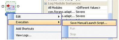
Figure 6: Saving launch script for manual launch
2. Select the file to save the properties for manual launch and click Save.
3. Follow the steps mentioned in the window that pops up to launch the component instance.
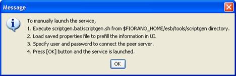
Figure 7: Pop up window showing the steps for launching the component instance manually
4. When this option is selected, properties Debug Mode is not visible and the value for property JVM_PARAMS is ignored.
None
If selected, the component instance is never launched. When this option is selected properties Debug Mode is not visible and the value for property JVM_PARAMS is ignored.
The boundary of the component is changed to provide a visual clue for the launch type. Figure 8 shows the change in the boundary of component instance for each launch type
Figure 8: Boundary of component instance with visual clue for launch type
Debug Mode
yes
The component instance is launched in debug mode. A debugger from any IDE can be attached to the component instance to debug the component instance step by step at runtime. When this value is selected, the property Debug Port is visible.
no
The component instance is not launched in debug mode and a debugger cannot be attached. When this value is selected, the property Debug Port is visible.
This property is only used when the property Launch Type is set to Separate Process. To debug the component instance launched in the memory of Peer Server JVM, debug parameters have to be in the configuration file %FIORANO_HOME%\esb\fps\bin\fps.conf of the Peer Server.
Debug Port
The port on which the component waits for instructions from debugger.
When property Debug Mode is set to yes, then the property Debug Port is set to 5000. It is equivalent to launching the component with the following command line arguments.
-Xdebug -Xrunjdwp:transport=dt_socket,server=y,suspend=n,address=5000
Note: The component instance can be alternatively launched in debug mode by specifying the required command line arguments in the property JVM_PARAMS.
This group contains different loggers that are used and their log level configuration.
All the loggers that are used by the component instance are shown as properties in this section. The level at which logging should be performed for each of the logger is defined. There are nine logging level available in the drop-down list Off, Severe, Warning, Config, Info, Fine, Finer, Finest, and All.
For information about log levels and the effect they have on logs generated, please refer to http://java.sun.com/j2se/1.4.2/docs/api/java/util/logging/Level.html.
The levels of all the loggers can be changed together by selecting required log level for the property All Modules.
This group contains a single property JVM_PARAMS which contains all command line parameters that are passed to launch the component. This property is used only when the Launch Type of the component instance is set to Separate Process. Any system properties can be set using this property.
Example: To support regional language specific characters during HTTP transfer, character set encoding of the regional language has to be specified using the system property file.encoding. The system property can be provided as -Dfile.encoding=<required_encoding> for this property. If there are some other properties already defined, then the value to add should be appended to the existing value separated by a space.
Input port properties appear in the Properties pane when an input port of a component instance is selected. Input port properties for a SMTP component are shown in Figure 9.
Figure 9: Input port properties for a SMTP component instance
The properties in the Authentication group are not used by pre-built components provided by Fiorano. However, they can be used in custom components.
This group contains properties related to destinations created for the ports of the component.
Destination Type
Specifies whether the destination for the port is a Queue or a Topic. Visual representation of port is changed based on the type of the destination as shown in Figure 10. A square indicates a queue and a circle indicates a topic.
Figure 10: Input port as queue and as topic
When this property is set to Topic, the property Durable Subscription is visible.
When this property is set to Queue, the property Durable Subscription is not visible.
Use Specified Destination
Destinations for each port in the application are created automatically and associated with a port when the application is launched. The destination name for destination created and associated to a port is constructed using the following function <Event Process GUID>__<Component instance name>__<Port name>
Example: If an Event Process whose GUID is SAMPLE_APP contains a SMTP component instance with name MAIL_SENDER. The destination created for the input port is SAMPLE_APP__MAIL_SENDER__IN_PORT.
However, if the destination to be used has to explicitly defined, then this property should be set to yes.
When this property is set to yes, the property Destination Name is visible.
When this property is set to no, the property Destination Name is not visible.
Destination Name
The name of topic or queue that has to be associated with the port. The destination is automatically created if it is not present.
This group contains properties related to JMS messaging concepts. In general, pre-built components provided by Fiorano use a single connection and share same session for reading messages on input port and sending messages on the output port.
Transacted
Specifies whether the JMS session is transacted or not.
yes
JMS session is created as a transacted session. Multiple input messages can be grouped into a single transaction. Messages are not sent on the output port of the component until the transaction is complete. They are held in-memory of the component. When this value is selected, property Transaction Size is visible.
no
JMS session is created as a non-transacted session. Messages are sent on the output port of the component immediately. When this value is selected, property Transaction Size is visible.
Note:
When the output of component is very large, it is not advised to set this property value to yes.
A transaction is based on the number of input messages processed and not based on the number of output messages sent. In cases, where a component sends a large number of output messages for each input request, it is not advised to set this property value to yes even if value for property Transaction Size is set to 1.
Example: A File Reader component reading a large binary file or a DB component that returns result set containing a large number of rows.
Transaction Size
Number of input messages that should be processed before committing the transaction.
Number of Sessions
Number of sessions that are created by the component instance to process messages received on the input port. Messages are processed in a separate session by each thread. This property is used to increase the number of threads that can process the requests and thereby increase the through put. However, the number of threads that can at a time is restricted by Max Pool Size property in Connection Pooling Configuration panel.
Acknowledgement Mode
Specifies the acknowledgement mode that is used to acknowledge messages. Messages are not deleted from destinations until they are acknowledged. When the component fails over because of the HA fail over of Peer Server, all the messages that are not acknowledged are redelivered. The number of duplicate messages in case of fail over can be controlled using this property.
DUPS_OK_ACKNOWLEDGE
Messages are acknowledged after configured number of messages are successfully processed and output messages are sent by the component instance. The number of messages after which the messages are acknowledged can be configured at the following node in FMQ profile Fiorano > mq > pubsub > TopicSubSystem > DupsOkBatchSize. Number of duplicate messages is utmost the DupsOkBatchSize for each session on each input port of the component instance.
AUTO_ACKNOWLEDGE
Messages are acknowledged after a message is successfully processed and the output message is sent by the component instance. Hence, number of duplicate messages is utmost 1 for each session on each input port of the component instance.
CLIENT_ACKNOWLEDGE
Pre-built components provided by Fiorano do not support this mode of acknowledgement.
This property is ignored if the property Transacted is set to yes. When the property Transacted is set to yes, messages are acknowledged when the transaction is committed. Hence, number of duplicate messages is utmost the number denoted by property Transaction Size for each session on each input port of the component instance.
Durable Subscription
Specifies whether a durable subscriber is created on the destination represented by the input port or not. This property is visible only when value for the property Destination Type is set to Topic.
yes
A durable subscription is created to the topic represented by the input port.
Messages sent to the topic are not lost when the component fails over because of the HA fail over of Peer Server.
If selected, then the property Subscription Name is visible.
no
A durable subscription is created to the topic represented by the input port.
Messages sent to the topic may be lost when the component fails over because of the HA fail over of Peer Server.
Note:
If the Destination Type is Queue, then messages are not lost when the component fails over because of the HA fail over of Peer Server.
Following components do not create durable subscriptions and hence have to use only queues as input ports Aggregator, Chat, Display, HTTPReceive, HTTPStub, Join, SAPR3Monitor, Sleep, WSStub, and XMLVerification.
Subscription Name
Subscription name that should used be when creating a durable subscriber. This should be a unique name for the Peer Server on which the component instance is running.
Client ID
Unique ID for the JMS connection created by this port. This property is not used by pre-built components provided by Fiorano as there is only one connection created for each component instance.
Message Selector
Specifies a condition (JMS Message Selector) to select only a particular set of messages. For information on message selectors, refer to Message Selectors section in the link http://java.sun.com/j2ee/sdk_1.3/techdocs/api/javax/jms/Message.html.
Output port properties appear in the Properties pane when an output of a component instance is selected. Output port properties for a SMTP component are shown in Figure 11.
Figure 11: Input port as queue and as topic
The properties in the Authentication group are not used by pre-built components provided by Fiorano. However, they can be used in custom components.
This group contains properties related to destinations created for the ports of the component. For more information, refer to section JMS Destination under Input Port Properties.
Time to Live
Specifies the time in milliseconds for which the message is available from the system after it is sent from the producer. The message is discarded on the expiration of this time. 0 (zero) milliseconds indicate infinite life time.
Example: Consider an application contains four component instances. Value for this property is set to 30000 milliseconds on the output port of the first component instance. This means, once the message is sent on the output port of first component instance, the message should be consumed by the fourth component instance in 30 seconds. If it is not consumed in 30 seconds, then the message will be lost and will never reach the fourth component.
Client ID
Unique ID for the JMS connection is created by this port. This property is not used by pre-built components provided by Fiorano as there is only one connection created for each component instance.
Message Priority
The priority of the message sent, can be any integer value from 0 (zero - lowest) to 9 (nine - highest). The default priority is 4.
Persistent
Specifies whether the producer on this port sends persistent messages or not. If this property is set to yes, all messages are persisted to message store. If this property is set to no, the messages are not persisted and there may be message loss noticed during the HA fail over of the Peer Server.
To avoid message loss in Fiorano Event Processes, change the following properties -
1. On each output port, set value of property Persistent to yes.
2. On each route, set value of property Durable to yes.
3. On each input port that is a topic, set value of property Durable Subscription to yes.
4. Whenever a JMS* component is used, make sure all messages sent are persistent and all subscriptions to topics are durable. These properties can be set in CPS of JMS components.
Some of the less used components in Fiorano have Acknowledgement Mode, Transaction Type and Transaction Size implicitly defined and will not pick the values from input port.
Aggregator AUTO_ACKNOWLEDGE, true, 1
Chat AUTO_ACKNOWLEDGE, false, 1
DiskUsageMonitorService AUTO_ACKNOWLEDGE, true, 1
Display AUTO_ACKNOWLEDGE, false, 1
ExceptionListener AUTO_ACKNOWLEDGE, false, 1
Feeder AUTO_ACKNOWLEDGE, false, 1
HTTPReceive AUTO_ACKNOWLEDGE, false, 1
HTTPStub DUPS_OK_ACKNOWLEDGE, false, 1
Join AUTO_ACKNOWLEDGE, from command line, 1
SAPR3Monitor AUTO_ACKNOWLEDGE, false, 1
Sleep AUTO_ACKNOWLEDGE, false, 1
Timer AUTO_ACKNOWLEDGE, true, 1
WSStub DUPS_OK_ACKNOWLEDGE, false, 1
XMLVerification AUTO_ACKNOWLEDGE, true, 1
Connection Pool Params
Defines the connection pool settings for the component. Creating a connection to external systems like Database or FTP Server or HTTP Server is typically a resource extensive and time consuming process. Configuring a connection pool reduces the overhead of creating a connection on each request.
Click the ellipses button
![]() to launch an editor
to configure connection pool parameters as shown in Figure 12
to launch an editor
to configure connection pool parameters as shown in Figure 12
Figure 12: Connection pool configurations
Enable Connection Pool
If this property is selected, the connections created are cached in a pool for subsequent use. When the connection pool is disabled it implies that the connection should not be cached and a new connection will be created for each request.
Enabling connection pool property will reduce the time spent in creating a new connection for every input request.
Properties Max Pool Size, Blocking Timeout and Idle Timeout are enabled only when this property is selected.
Max Pool Size
The maximum number of connections that can be cached in the pool.
Blocking Timeout (in ms)
The time in milliseconds after which the call to fetch a connection from the pool will timeout, if there is no unused connection available. Connection will not be created after timeout.
Idle Timeout (in mins)
The time in minutes after which the idle connections are returned to the pool.
Proxy Settings
Click the ellipses button
![]() to launch an editor
to configure proxy configurations as shown in Figure 13.
to launch an editor
to configure proxy configurations as shown in Figure 13.
Figure 13: Proxy configurations
Use Proxy Server
Select this option if the connection has to be established using a proxy server. Properties Proxy Address, Port Number, Username, Password and SOCKS Proxy.
Proxy Address
The IP address or the host name of the machine where the proxy server is running.
Port Number
Port number on which the proxy server is running.
Username
The user name with which the user can login to the proxy server.
Password
Password for the user name provided.
SOCKS Proxy
Enable this property to use SOCKS protocol to connect to the proxy server.
Click the ellipses button
![]() to launch an editor
to configure SSL configurations as shown in Figure 14.
to launch an editor
to configure SSL configurations as shown in Figure 14.
Figure 14: SSL configurations
Enable SSL
Select this option to enable SSL Settings. Rest of the properties in this editor are enabled and configurable only when this property is checked.
Trust Store Location
Location of the trust store file. TrustStore is a file where digital certificates of trusted sites are stored and retrieved for authentication during an SSL connection. TrustStore is used to authenticate a server in SSL authentication.
Trust Store Password
Password of the specified trust store.
Key Store Location
Location of the key store file. The KeyStore is used by the component for client authentication.
Key Store Password
Password of the specified key store.
Key Store Type
Type of the Key Store whose location is specified by Key Store Location.
Trust Store Type
Type of Trust Store whose location is specified by property Trust Store Location.
Trust Manager Factory Type
Algorithm for the Trust Manager Factory.
Key Manager Factory Type
Algorithm for the Key Manager Factory.
Security Provider Class
Determines Security provider class.
Security Protocol
Determines Security protocol
Key Store Client Key
Determines Key Store Client Key
Note: For more information on SSL Configurations, please refer to Section 3.12 Public Key, Cryptographic Keystore and Truststore in Fiorano SOA User Guide.
Figure 15: Common configurations in Interaction Spec panel
Validate Input
no -
The input is not validated and is directly processed by the component. Exception may occur while processing if the message is invalid.
Yes -
The input is validated against the structure specified on the input port of the component. If it is not valid, exception occurs and further processing is not done.
Cleanup resources (excluding connection) after each document
A component creates various objects to process business logic. Some of these objects are connection objects or are related to connection where as other objects are not related to connection but are required to process business logic. Holding these objects in-memory all the time will make lesser memory available that can be freed and deleting these objects to free up space results in higher processing time as the objects have to be recreated. Hence, the objects related to business logic can be removed from time to time.
no
When this option is selected, objects that are not connection related are destroyed and recreated for each request.
Yes
When this option is selected, objects that are not connection related are not destroyed and are reused for each request.
Note: When a connection object is destroyed all objects are recreated on subsequent request.
Target Namespace
Two or more XML schema having same namespace will cause problems if there are elements which are defined with same name. Schema set on the input and output ports of the component are in some created by the component. To avoid the clash of elements from different schema, the schema generated by the component use the value provided for this property to compute the namespace for input or output schema.
Monitoring Configuration
When monitoring is enabled for a component the following statistics are sent to FPS_USER_EVENTS_TOPIC at configured intervals of time
Minimum execution time
The minimum amount of time taken to process any message during the last publish interval.
Maximum execution time
The maximum amount of time taken to process any message during the last publish interval.
Count
Number of messages processed during the last publish interval.
Throughput
Rate at which messages are processed during the last publish interval.
Click the ellipses button
![]() to launch an editor to configure monitoring configurations
as shown in Figure 16.
to launch an editor to configure monitoring configurations
as shown in Figure 16.
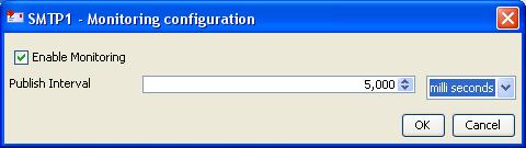
Figure 16: Monitoring configurations in Interaction Spec panel
Enable Monitoring
Select the check box to enable monitoring for request execution time.
Publish Interval
The time interval after which monitoring statistics are computed and sent.
To view the monitoring statistics in dashboard, open FES profile and navigate to FES > Fiorano > Esb > Events > FESEventsManager. Click on FESEventsManager and set the property ListenForUserEvents to yes in the properties window.
A component can be scheduled to execute fixed request at configured intervals of time. When the component is configured to run in scheduler mode the component will not have input port. However, messaging properties that are usually configured on the input port can be configured in Transport Configurations panel.
Figure 17: Scheduler configurations panel
Enable Scheduling
Select the check box to run the component in the scheduling mode.
Interval between polls
Specifies time interval between successive requests.
Number of polls
Number of times the input request is executed.
Infinite times
If this option is enabled, then the number of times the input request is executed will be infinite.
Start time
The polling start time. If the specified start time is earlier then the component start time, the first schedule will happen at the next scheduled time. For example, start time is 08:00:00, poll interval is 30 minutes, and component starts at 8:10:00, the first schedule will happen at 08:30:00.
Start date
The polling start date. If the specified start date is earlier then the component start date, then it will be ignored and input messages are sent at next scheduled date.
Use specified Input
Select the check box to configure input that is repeatedly executed.
Validate
Validates the specified input against the structure specified on the input port.
Generate Sample Input
Generates the sample input for the structure specified on the input port.
Transport Configurations panel is used to configure messaging properties when the component is configured in scheduling mode. These properties are configured on the input port when the component is not in scheduling mode.
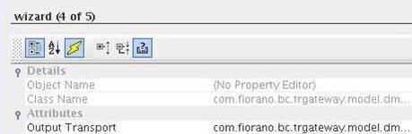
Figure 18: Transport configurations panel
Output Transport
Click the ellipses button
![]() to launch an editor
for configuring transport properties. The properties in the editor are
shown in Figure 19.
to launch an editor
for configuring transport properties. The properties in the editor are
shown in Figure 19.
Figure 19: Transport properties
Acknowledgement Mode
Valid values for this field are 1 to indicate AUTO_ACKNOWLEDGE, 2 to indicate CLIENT_ACKNOWLEDGE and 3 to indicate DUPS_OK_ACKNOWLEDGE. Any other value will throw an exception and component will not be started.
For information on acknowledgement modes, refer to section Acknowledgement Mode in Input Port Properties.
Enable request-reply
If this property is set to yes, then responses will be sent to JMSReplyTo port if it is present, else response is sent on the output port of the component.
Transacted
For information on this property, refer to section Transacted in Input Port Properties.
Transaction Size
For information on this property, refer to section Transaction Size in Input Port Properties.
Errors that occur in the component are classified into three categories Request Processing Error, Connection Error and Invalid Request Error. Actions that have to be taken when an error occurs are defined in the Error Handling panel.
Figure 20: Error handling
Request Processing Errors are categorized based on the following conditions -
The error occurs after input message is successfully parsed and understood.
The error is not a result of connection problems.
Example: In case of FTPGet, a Request Processing Error occurs when the specified file (to be downloaded) in the input request is not present in FTP Server.
Figure 21: Available actions for Request Processing Error category
Remedial Actions
Actions that can be taken when a Request Processing Error occurs is shown in Figure 21.
Re-execute Request
The component will re-execute the input request if this option is enabled. Configuring for retries is explained in Retry Configuration section. This option should be enabled only for errors that can be rectified over time.
Example: Error in file reader because a file is not found. If the required file should be placed by another process, then the file not found error can be rectified over time and hence can be retried.
Throw fault on warnings
In some cases, a problem in the component which is not severe is treated as a warning. Such warnings are just logged by default. If this property is enabled, the component will treat such warnings as errors.
Example: When the FileReader is configured to read files with a particular pattern for file names, a warning is logged if there are no files whose names matches the configured pattern. If the FileReader is polling a directory, then it is an inherent assumption that files are not always present and hence treating it as warning is appropriate. But if the file reader is not in scheduler mode, then absence of files has to be treated as an error.
Send To Error Port
If this option is enabled, the component will send the error on the ON_EXCEPTION output port of the component. By default, ON_EXCEPTION port is present in all components that support error handling. If this option is unchecked, then the Retries before sending error property in Advanced Settings group is disabled.
Stop Service
The component is stopped when an error occurs if this action is enabled.
This property in Error Handling Panel will be visible only if the Managed Connection Factory panel is present. Presence of Managed Connection Factory implies that the component makes a connection to external system.
Example: Components like FileReader and FileWriter do not create any connections and hence they do not have this property in the CPS.
Errors that occur because of the connection to an external system cannot be made or because the connection to an external system is lost are categorized under the category Connection Error.
Example: Trying to connect to an external web site when the network connection is not active.
Figure 22: Available actions for Connection Error category
Remedial Actions
Actions that can be taken when a Connection Error occurs is shown in Figure 22.
Discard Connection
The component removes the connection from the connection pool as soon as a connection error occurs. Subsequent request uses a new connection from the connection pool.
Try reconnection
The component will re-execute the input request with a new connection, if this action is enabled. Configuring for retries is explained in Retry Configuration section.
Send To Error Port
The component will send the error on the ON_EXCEPTION output port of the component if this action is enabled. By default, ON_EXCEPTION port is present in all components that support error handling. If this option is unchecked, then the Retries before sending error property in Advanced Settings group is disabled.
Stop Service
The component is stopped when an error occurs if this action is enabled.
Errors that occur when parsing the input request are categorized under Invalid Request Error.
Figure 23: Available actions for Invalid Request Error category
Remedial Actions
Send To Error Port
The component will send the error on the ON_EXCEPTION output port of the component if this action is enabled. By default, ON_EXCEPTION port is present in all components that support error handling. If this option is unchecked, then the Retries before sending error property in Advanced Settings group is disabled.
Do not stop service
If this property is not checked, when an invalid input is sent to the component, the component will be stopped immediately. By default this property is enabled.
Example: In case of SMTP, if the input message is not valid according to the schema set on its IN_PORT, an exception occurs and the component will be stopped only if this property is unchecked.
When Re-execute Request is enabled for Request Processing Error or when Try Reconnection is enabled for Connection Error, the Advanced Settings group containing configurations for retries is visible.
Time between retries(ms)
The time interval between two successive retries.
Number of retries
The number of times the component should retry the request. This property is enabled only if Infinite check box is unselected.
Infinite
If the check box is selected, the component will continuously retry the request until the request is process successfully. when this option is selected, the property Number of retries is disabled and its value is ignored.
Retries before sending error
This property is enabled only if Send To Error Port action is enabled. If Send To Error Port action is enabled and if the value for this component is a number n, then the component sends an error on the ON_EXCEPTION port after every n retries.
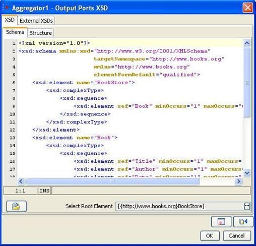
Figure 24: Schema Editor
Schema Editor is used to configure schemas that are required for the functionality of a component.
In general,
XSDs and DTDs can both be provided in the schema editor. Some components allow only XSDs.
Only one root element can be selected. Some components allow selecting multiple root elements.
When a DTD is provided in the schema editor, the External XSDs tab is disabled.
XSD Schema tab
XSD/DTD can be provided in the text area in the schema tab shown
in figure 24. Schemas that are present on the file system can be loaded
by clicking on Load button
![]() . This opens a file browser
which enables navigation to the required schema on the file system. The
file type can be chosen as XSD or DTD in the filechooser.
. This opens a file browser
which enables navigation to the required schema on the file system. The
file type can be chosen as XSD or DTD in the filechooser.
Root element can be selected by clicking on Select Root Element button
![]() . A list containing all the elements present in the schema
will be displayed as shown in Figure 25. A root element (multiple root
elements, in some cases) should be selected from that list of elements.
The selected root element(s) will be displayed in the schema editor next
to Select Root Element text.
. A list containing all the elements present in the schema
will be displayed as shown in Figure 25. A root element (multiple root
elements, in some cases) should be selected from that list of elements.
The selected root element(s) will be displayed in the schema editor next
to Select Root Element text.
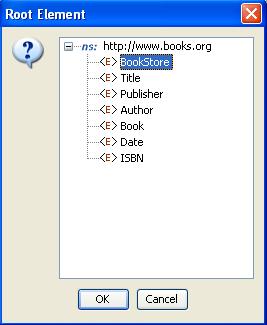
Figure 25: Selection of root element
XSD Structure tab
The structure tab displays a tree structure of the schema provided as shown in figure 26. The structure depends on root element.
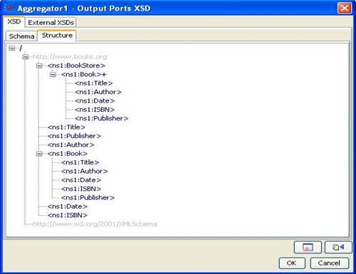
Figure 26: Structure of the schema when no Root Element is chosen
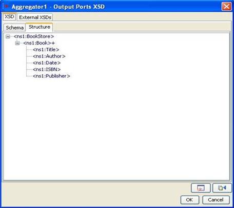
Figure 27: Structure of the schema when Bookstore is chosen as Root Element
The structure of the entire schema is displayed if none of the root element is selected. If root element is selected (as Bookstore in the Figure 27), the structure of that element is displayed.
External XSDs tab
If there are any imported schemas in the schema provided in XSD-Schema tab, they can be resolved by adding them as the external XSDs here. Any number of external schemas can be added here.
Note: Imported schemas can also be resolved by adding the schemas in Schema Repository.
Schemas provided as external XSDs must have target namespace defined.
Click on the Add button to add the external schema. Select an option from Manual or Load from File.
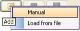
Figure 28:
Adding external schema
Manual - The text editor on the right is editable only when Manual option is selected. The schema has to be provided manually in the text editor.
Load from File - Opens a File Chooser to browse the required external schema.
After loading the schema in the text editor, click on Save button
![]() to save the schema. The schema will be added to
the list of external XSDs only when it is saved.
to save the schema. The schema will be added to
the list of external XSDs only when it is saved.
To remove a schema, select the corresponding namespace and click Remove
button
![]() .
.
To view a schema, select the corresponding namespace and the schema can be viewed in the text editor.
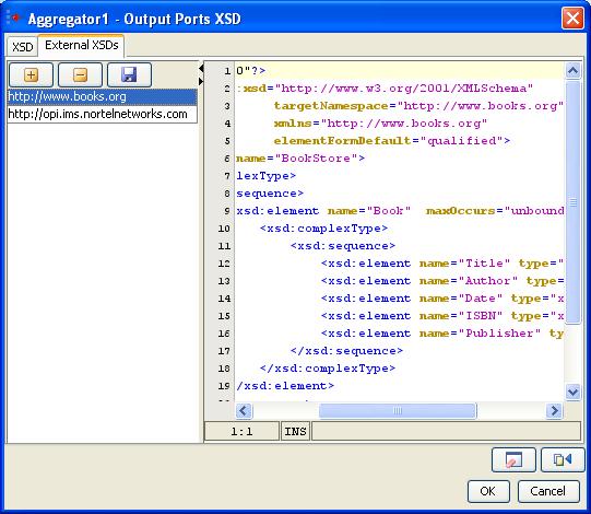
Figure 29: Configuring external schema
Clear
![]()
On clicking Clear button, the schema, external schemas, root element and structure present in the schema editor will be cleared.
Fetch from Connected Source
![]()
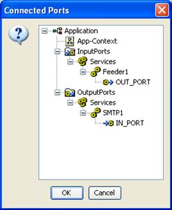
Figure 30: List of connected ports from which schema should be fetched
On clicking Fetch from Connected Source button, a list of ports (which have schema set on them) of the components connected to this component are displayed. Application Context of the event process is also listed, if defined. On selecting one of the ports or application context, the schema present will be set as schema in the schema editor.
Schema Repository is used to store schemas that are imported in schemas used by different components/event processes. The imported schemas referred from anywhere in an Event Process/component can be stored here so that they are resolved even when they are not added explicitly. Hence, schemas which are imported across multiple event processes/components can be stored in the schema repository.
To add schemas to the Schema Repository, perform the following steps.
In Studio, navigate to Tools -> Schema Repository. This opens a Schema Repository editor as shown in Figure 31 using which schemas can be added to schema repository.
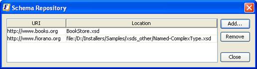
Figure 31: Schema repository editor
Click on Add... Button to add schemas to the repository, Customize Add... editor shown in Figure 32 will be opened.
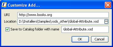
Figure 32: Adding XSD to the schema repository
Click
on ![]() to browse the required XSD.
to browse the required XSD.
Select an XSD and click OK
The values URI, Location, schema name will be automatically updated.
The URI value should not be an empty field. In case, if the schema has a target namespace, URI should be same as the target namespace of the XSD.
The Location field displays the absolute path of the schema file.
If the schema is to be copied and saved in the location <FIORANO_HOME>/xml-catalog/user, select the field Save to Catalog folder with name and specify a name with which the file has to be saved.
If Save to Catalog folder with name is not selected, the file is not copied to the location <FIORANO_HOME>/xml-catalog/user and will be referred from its original location.
Click on OK to close Customize Add... editor.
A new row specifying the URI and Location of the XSD will be added in the table.
To remove a schema from the schema repository, select a row from the table and click Remove.
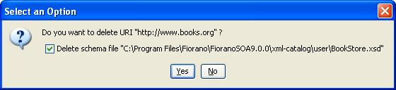
Figure 33: Removing XSD from the schema repository
The option 'Delete schema file' specifies whether to delete the file from the system or just to remove the schema from xml-catalog. Select the check box to remove the file completely.
In case, if the file is not copied to <FIORANO_HOME>/xml-catalog/user, the file will be deleted from its original location if this option is selected.
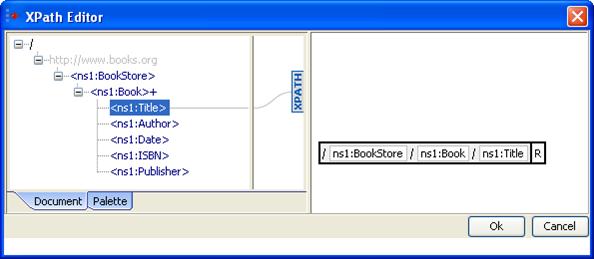
Figure 34: XPath Editor
XPath Editor can be used for specifying path expressions to identify nodes in an XML document and for specifying conditions. The list of elements from schema provided are shown in the left panel of the editor. An XPath Editor with sample schema is shown in Figure 34.
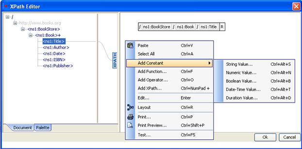
Figure 35: Adding a constant in XPath Editor
An element can be selected by simple drag and drop onto the right panel. An XPath expression may consist of different constant values, functions or/and operators. These can be added easily by right clicking on the right panel and selecting the option based on the requirement as shown in Figure 35.
Adding a Function: A function can be added either by right clicking on the right hand side panel --> Add Function or by selecting from the list available in the palette tab which is present in the left panel as shown in figure 36.
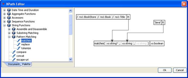
Figure 36: XPath Editor Palette containing different XPath functions
A string function matches which takes two arguments and returns a boolean value is shown in the Figure 36.
Adding a Constant value: Supported types of constants are String,Boolean,Numeric,Date-Time,Duration.
Example: Addition of a boolean value can be done as described below
Right-click on the right panel. Select Add Constant -->Boolean Value.
Select the value as shown in Figure 37.
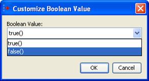
Figure 37: Adding a boolean constant
Addition of a Operator:
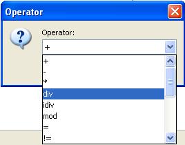
Figure 38: Adding an operator
Right-click on the right panel. Click on Add Operator.
Select the operator as shown in Figure 38.
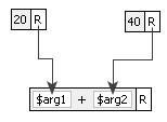
Figure 39: Add(+) operator
Figure 39 illustrates a sample Xpath expression using a + operator. It contains two numeric constant values which are passed as arguments to the operator.
Copyright © 1999-2008, Fiorano Software Technologies Pvt. Ltd. All rights reserved.
Copyright © 2008-2009, Fiorano Software Pty. Ltd. All rights reserved.
This software is the confidential and proprietary information of Fiorano Software ("Confidential Information"). You shall not disclose such Confidential Information and shall use it only in accordance with the terms of the license agreement enclosed with this product or entered into with Fiorano.