...
When an Input Structure node can have multiple instances and the user wants to define a mapping for each one of them, then For-Each mapping should be used. A necessary condition for this type of mapping is that the Output Structure node to which For-Each Mapping is being defined should be of[ZERO-MANY] or [ONE-MANY] cardinality. The figure below shows an instance of a For-Each mapping.
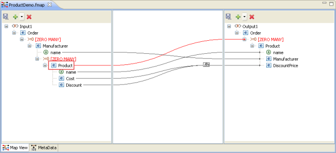
Figure 6: For-Each Mapping
...
The following example illustrates this situation. A Student DTD has two types of child elements: male and female. These need to be mapped to the student element in the output structure DTD.

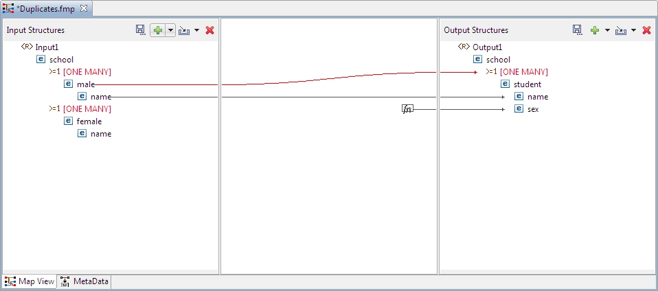
Figure 7: Mapping a node to One Many control node
The same mapping has to be defined for the female elements. To do this, drag the female node from the input structure to the ONE MANY node in output structure. A message dialog box is displayed in the figure below.

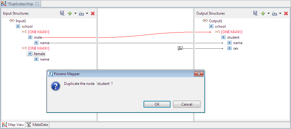
Figure 8: A shortcut menu prompts you to duplicate the node
Click OK in the message dialog box to create a duplicate node. A mapping is created as shown in the figure below.
| Note |
|---|
If the replicated node does not appear, right-click ONE MANY in the Output Structures panel and click Expand All option. |
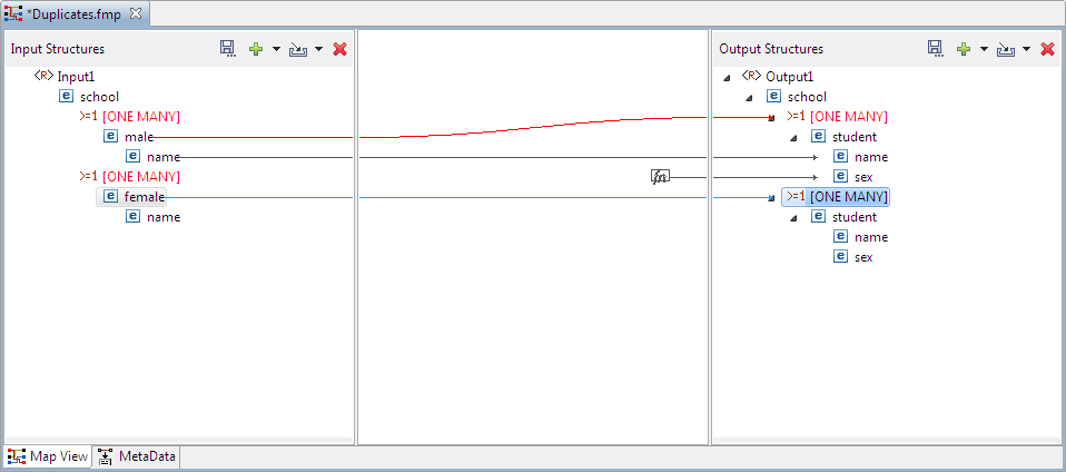
Figure 9: The One Many Node is Duplicated
...
Select the nodes in the Input and Output Structure whose child nodes are mapped. Click the Child to Child option in the tool bar.

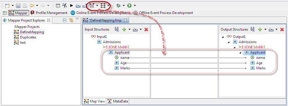
Figure 10: Creating Automatic Mapping between child nodes
...
- Select the DiscountPrice output node, the Funclet View of the eMapper Perspective appears.

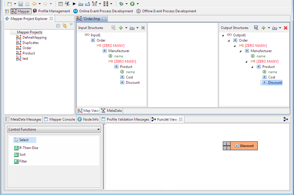
Figure 11: Selecting the Output Node for Mapping
- The selected Output node is automatically displayed in the Function easel, as shown in the Figure 11. To add an input structure node to the mapping, drag it to the Funclet easel of the Visual Expression Builder. Here, drag the Cost input node from the Input Structure Panel to the Funclet easel. The Cost input node is added to the Funclet easel as shown in figure 12.

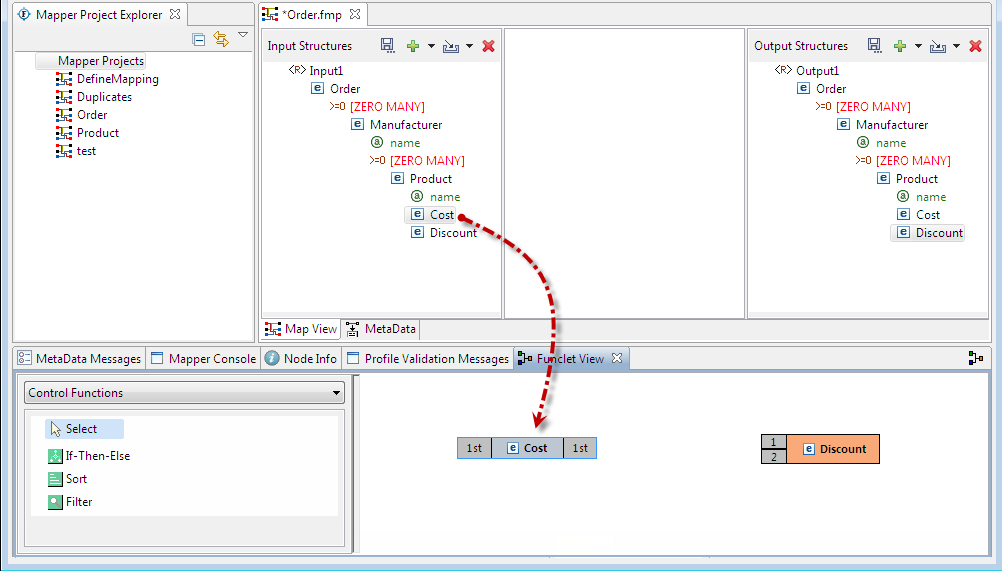
Figure 12: Dragging an Input node
- To subtract the value of Discount input node, the subtract function from the Funclet Palette can be used. The subtract function is available in the Arithmetic functions. To add the subtract function, click on the drop-down list in the Funclet palette and select the Arithmetic Functions from the list. The drop-down list is displayed in the Funclet palette as shown in Figure 13.
- The Arithmetic functions are displayed in the Funclet palette. Drag the subtract function from the Function palette to the Funclet easel. The subtract function is added to the Funclet easel as shown in Figure 14.

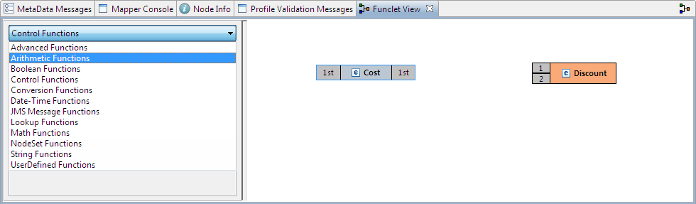
Figure 13: Selecting the Arithmetic Function Category in the Funclet palette
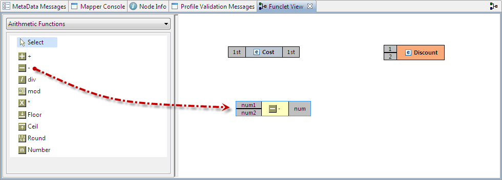
Figure 14: Adding the Subtract function
- Next, add
Add the Discount input node to the Funclet easel.

Note Move the Subtract function to place the Discount input node parallel to Cost node to form a neat layout.
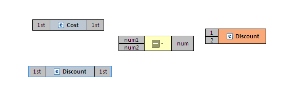
Figure 15: Adding another input node
- To define a mapping, links should be defined between these nodes. The Discount output is the difference between the Cost and Discount input nodes. To achieve this, the Cost and Discount nodes should be connected to the input pins (num1 and num2 respectively) of the subtract function and its output pin should be connected to the input pin of the Discount output node.

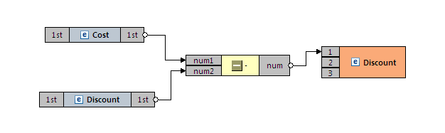
Figure 16: The final mapping is defined
- The required mapping is defined as shown in figure above.
...