...
- In Memory: The component instance is launched in the JVM of the Peer Server. It is automatically launched when the application is launched. When this option is selected properties Debug Mode and JVM_PARAMS are not visible.
Group Process: This launch mode enables multiple microservices to run in a Single JVM sharing the same resources. This launch mode overcomes certain limitations faced by the two modes mentioned above - the Separate launch mode having a restriction to use a limited number of microservices in a peer and the In Memory launch mode affecting the peer server performance when microservices face memory/thread leak.
Tip To know more about the 3 launch modes above, refer to the Configuring Execution Type section.
Manual: The component instance is not launched when the application is launched. It has to be launched manually from the command line.
launch the component manually -Tip To
...
know more about the Manual launch mode and for further details on using scriptgen, refer to the Manual Deployment section.
- None: If selected, the component instance is never launched. When this option is selected properties Debug Mode is not visible and the value for property JVM_PARAMS is ignored.
The boundary of the component icon is changed to provide a visual clue for the launch type selected. The below figure shows the change in the boundary of a component instance for each launch type.
![]()
Figure 97: Boundary of component instance providing visual clue for launch type
...
| Info |
|---|
By default, the log level is set to SEVERE. This can be changed to the desired level. For example, the log level can be set to CONFIG when working on the Development environment. |
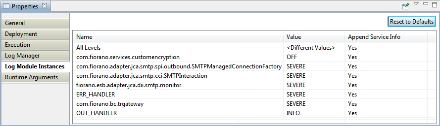
Figure 108: Log Module Instances properties in the Properties panel
...
Contains the information about the runtime arguments for the service. It has a single property JVM_PARAMS which contains all command line parameters that are passed to launch the component.
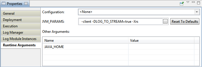
Figure 119: Execution properties in the Properties panel
...
JVM_PARAMS section contains the JVM parameters that are used while launching the component. Whenever a change is made in JVM PARAMS section, the Update all Service Instances dialog box appears asking whether the change has to be updated for all the service instances in all Event Process having the same JVM PARAMS value.
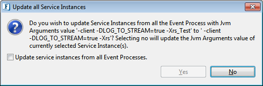
Figure 1210: Dialog box prompting to update all Service Instances or to update only the present instance
If No option is selected, then it updates to the current service instance. If Yes option is selected, a dialog listing the service instances with same JVM PARAMS value appears and the required service instances can be selected for an update.
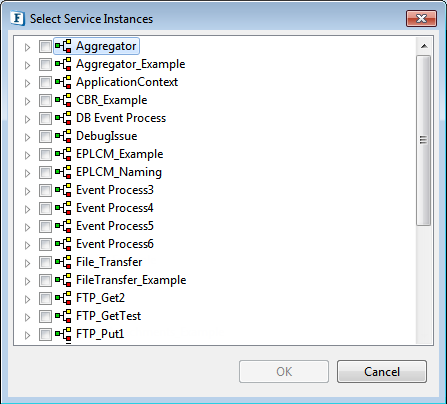
Figure 1311: Select Service Instances
...
Input port properties appear in the Properties pane when the input port of a component instance is selected.
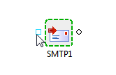
Figure 1412: Input Port properties selected/highlighted
...
| Anchor | ||||
|---|---|---|---|---|
|
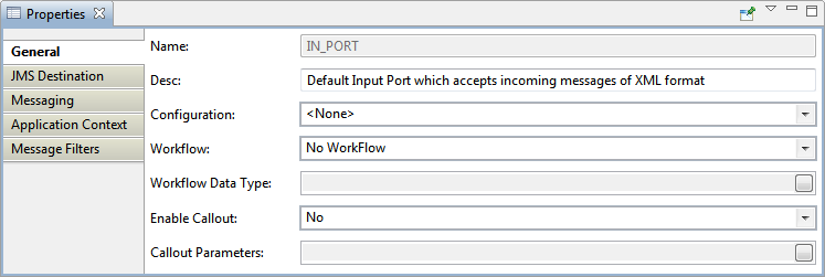
Figure 1513: Input port General properties for a sample component instance
...
| Note |
|---|
|
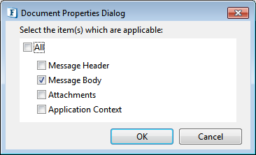
Figure 1614: Dialog box to choose Work Data Type
...
Specifies DB callout parameter types for the workflow.
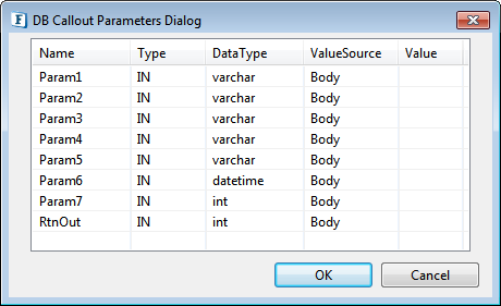
Figure 1715: Execution properties under Property panel
...
This group contains properties related to destinations created for the ports of the component.
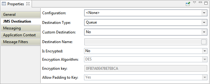
Figure 1816: Execution properties in the Input Port Properties panel
...
Specifies whether the destination for the port is 'Queue' or 'Topic'. Visual representation of port is changed based on the type of the destination as shown below. Square shape indicates a Queue and a circle indicates a Topic.
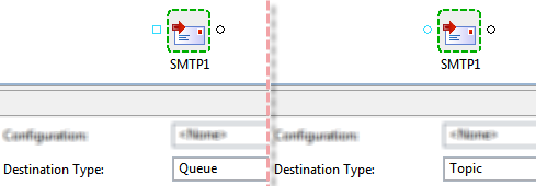
Figure 1917: Input port as queue and as topic
...
This group contains properties related to JMS messaging concepts. In general, pre-built components provided by Fiorano use a single connection and share the same session for reading messages in the input port and sending messages to the output port.
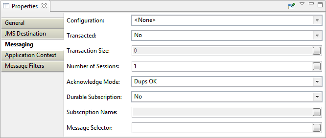
Figure 2018: Messaging properties in the Input Port Properties panel
...
Helps to manage the Application Context that is configured for the application / Event Process.
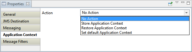
Figure 2119: Application Context properties in the Input Port Properties panel
...
Messages can be filtered by providing a specific name and value to it under the Name and Value columns respectively.
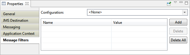
Figure 2220: Message Filters properties in the Input Port Properties panel
...
Output port properties appear in the Properties pane when an output of a component instance is selected.
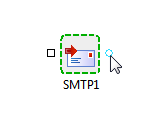
Figure 2321: Output port properties selected/highlighted
...
| Anchor | ||||
|---|---|---|---|---|
|
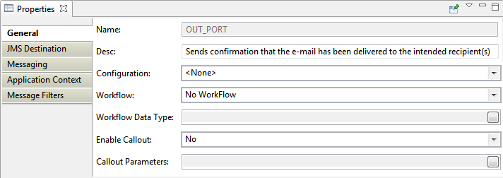
Figure 2422: Output port General properties for a sample component instance
...
| Anchor | ||||
|---|---|---|---|---|
|
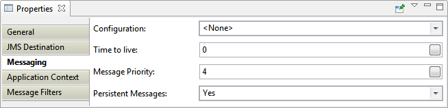
Figure 2523: Messaging properties in the Output Port Properties panel
...
In the Output Port Application Context, you have an option to choose the Component Instance from the Configuration drop-down if it was saved after creating the Application Context. Rest of the options are the same as in Input Port properties.
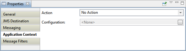
Figure 2624: Application Context properties in the Output Port Properties panel
...
Defines the connection pool settings for the component. Creating a connection to external systems like Database or FTP Server or HTTP Server is typically a resource extensive and time-consuming process. Configuring a connection pool reduces the overhead of creating a connection on each request.
Click the ellipsis button  to launch an editor to configure connection pool parameters as shown in the figure below.
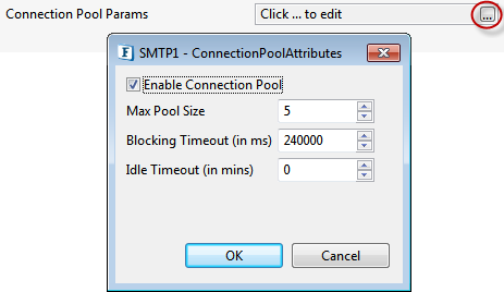
Figure 2725: Connection pool configurations
...
Click the ellipses button ![]() to launch an editor to configure proxy configurations as shown below.
to launch an editor to configure proxy configurations as shown below.
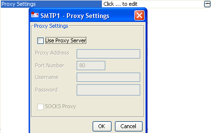
Figure 2826: Proxy configurations
Use Proxy Server
...
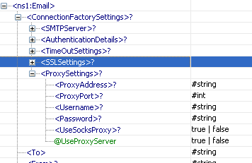
| Info |
|---|
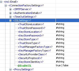
When the property Use Connection details from input is chosen, an element ProxySettings will be added to the schema of the input port of the component as shown in the figure below to provide the proxy details in the input message.
|
...
Click the SSL Security ellipsis button to launch the editor to set SSL configurations.
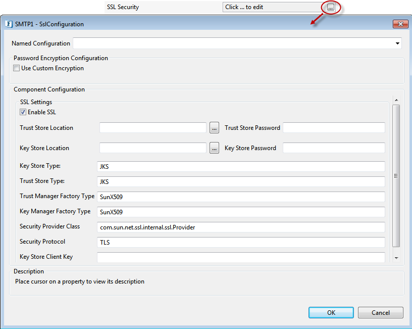
Figure 3028: SSL configurations
| Anchor | ||||
|---|---|---|---|---|
|
...
| Info |
|---|
|
...
| Anchor | ||||
|---|---|---|---|---|
|
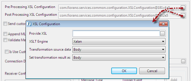
Figure 3230: Pre/Post Processing XSL Configuration properties
...
When this property is chosen as 'other' along with Transformer factory class property, it determines the transformer implementation that should be used to perform the transformation.
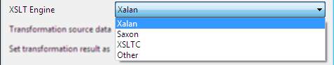
Figure 3331: XSLT Engine properties
Xalan (2.7.0) and Saxon (8.4) transformer implementations are bundled with Fiorano environment for performing transformations.
...
This property is used to apply transformation source to a particular part of the input message.
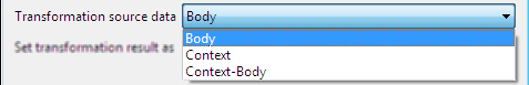
Figure 3432: Transformation source data properties
...
This property is used to set transformation result to a particular part of the output message.
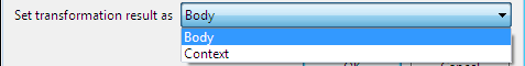
Figure 3533: Set transformation result as properties
...
The property helps components to skip certain messages from processing.
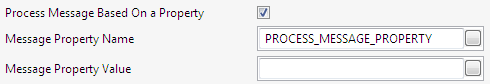
Figure 3634: Process Message Based On a Property settings
...
In an Event Process that is configured to listen for multiple types of HL7 messages using WSStub microservice, which forwards them using different protocols based on the HL7 message type and inserts it into database, only the forward action is successful. Generally, parallel flows are defined for each HL7 message type, route selectors used to identify the flow and thereby message is sent out of the parallel flow to the DB component.
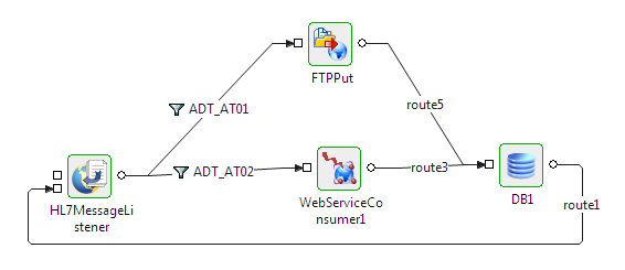
Figure 3735: Event Process composed as a normal parallel flow
It is difficult to maintain order at the DB component input port in above flow. To maintain the order, process all the messages sequentially as shown in the figure below and configure the Process Message Based on Property based on the HL7 message type; only the required components will process, others just forward the message to its output port.
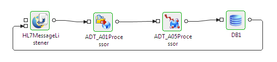
Figure 3836: Event Process composed with the property enabled in the HL7 microservice
| Anchor | ||||
|---|---|---|---|---|
|
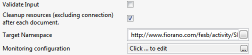
Figure 3937: Common configurations in Interaction Spec panel
...
Click the ellipsis button to launch an editor to configure Monitoring configuration.

Figure 4038: Monitoring configurations in Interaction Spec panel
...
- Open Profile Management and go to FES under Profiles.
- Navigate to FES > Fiorano > Esb > Events.
- Click FESEventsManager to open the Properties of FESEventsManager window on the right side.
Under ComponentInstance Configuration section, select the ListenForUserEvents checkbox.
Note Ensure that the Server is stopped to make the above changes.
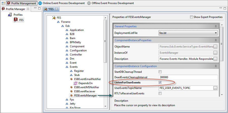
Figure 4139: Enabling Dashboard Monitoring option through eStudio
...
- Go to Advanced Properties property under Advanced Properties tab present in the Navigation Panel.
- In the Configure Advanced Property window, expand Enterprise Server>Events Manager.
- Under Action column, click the Change button corresponding to the Attribute Name: ListenForUserEvents.
- Change the value to "true" from the ListenForUserEvents drop-down and click OK.
- Click Save Configuration button in the Save Changes dialog box and notice the change in the Attribute Value parameter.
- Restart Server to bring the changes into effect.
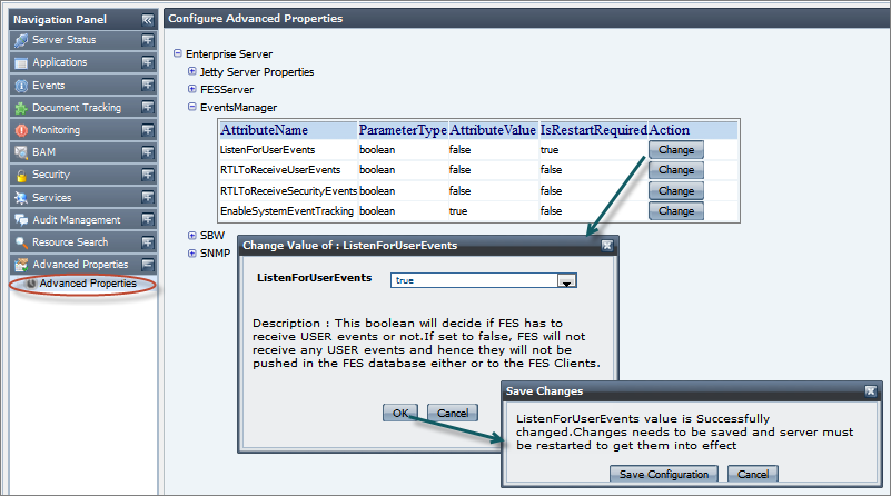
Figure 4240: Enabling Dashboard Monitoring option through Dashboard
...
A component can be scheduled to execute a specific request at configured intervals of time. When the component is configured to run in Scheduler mode, the component will not have input port (separate input need not be sent to the component in order to send message). However, messaging properties that are usually configured on the input port can be configured in Transport Configurations panel.
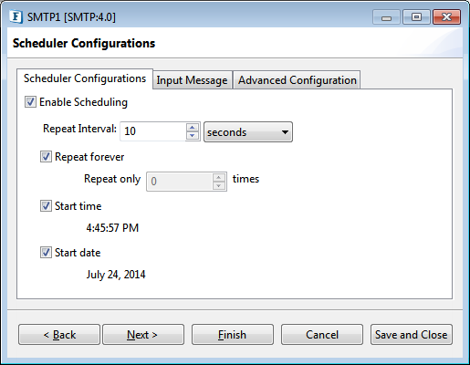
Figure 4341: Scheduler configurations panel
...
The polling start date. If the specified start date is earlier than the component start date, then it will be ignored and input messages are sent at next scheduled date.
Input Message
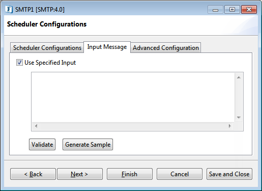
Figure 4442: Input Message tab in the Scheduler Configurations panel
...
Advanced scheduling information can be configured in the Scheduler Configuration panel.

Figure 4543: Advanced Scheduling configuration
...
Click the button against the property to specify the dates in the Editor. Dates moved to the Included Entries section are considered as the scheduled dates.
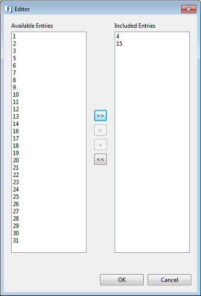
Figure 4644: Editor to provide Scheduled Dates In Month
Scheduled days in week (Schedule Type - WEEKLY)
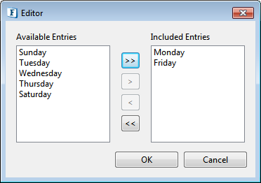
Figure 4745: Editor to provide Scheduled days in week
...
After selecting the Enable Scheduling check box in the Scheduler Configuration panel, click Next to configure Transport properties in Transport Configurations panel.
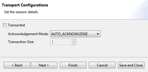
Figure 4846: Transport configurations panel
...
| Note |
|---|
Some of the panels or actions are not available for some components and hence are not visible in those components. |
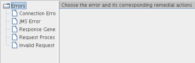
Figure 4947: Error handling
| Anchor | ||||
|---|---|---|---|---|
|
...
Example: Trying to connect to an external web site when the network connection is not active.
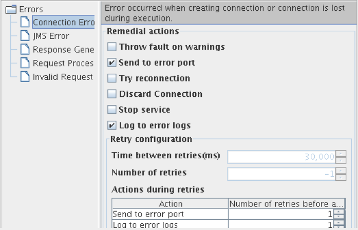
Figure 5048: Available actions for Connection Error category
...
Errors that occur in transport (JMS)
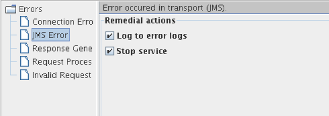
Figure 4449: Available actions for JMS Error category
...
Errors that occur while building a response for the processed request.
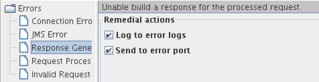
Figure 4550: Available actions for Response Generation Error category
...
Example: In case of FTPGet, a Request Processing Error occurs when the specified file (to be downloaded) in the input request is not present in FTP Server.
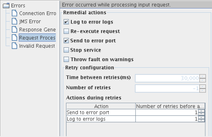
Figure 4651: Available actions for Request Processing Error category
...
Errors that occur when parsing the input request are categorized under Invalid Request Error. Remedial actions are different for EDBC and BC components.
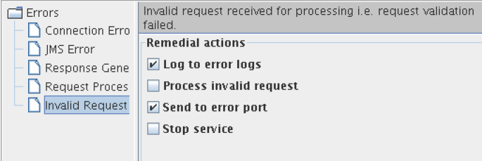
Figure 4752: Available actions for Invalid Request Error category
...
| Anchor | ||||
|---|---|---|---|---|
|
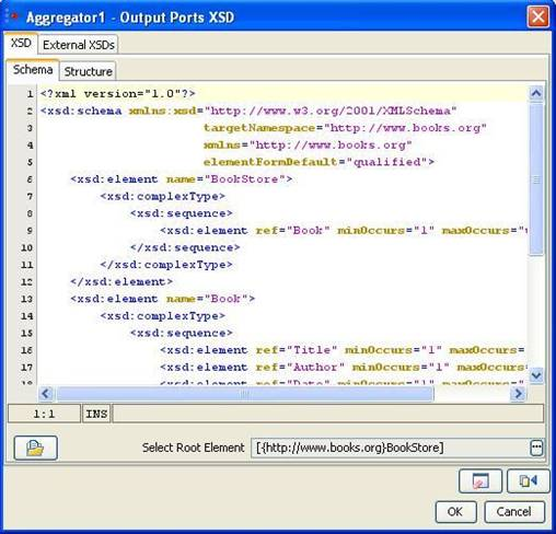
Figure 4853: Schema Editor
Schema Editor is used to configure schemas that are required for the functionality of a component.
In general,
...
Root element can be selected by clicking on Select Root Element button ![]() . A list containing all the elements present in the schema will be displayed as shown in Figure 49. A root element (multiple root elements, in some cases) should be selected from that list of elements. The selected root element(s) will be displayed in the schema editor next to Select Root Element text.
. A list containing all the elements present in the schema will be displayed as shown in Figure 49. A root element (multiple root elements, in some cases) should be selected from that list of elements. The selected root element(s) will be displayed in the schema editor next to Select Root Element text.
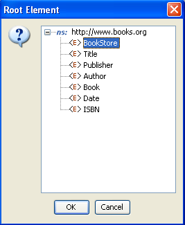
Figure 4954: Selection of root element
...
The structure tab displays a tree structure of the schema provided as shown below. The structure depends on root element.
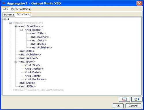
Figure 5055: Structure of the schema when no Root Element is chosen
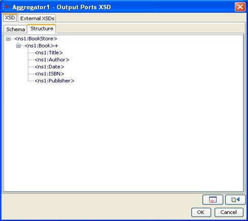
Figure 5156: Structure of the schema when Bookstore is chosen as Root Element
...
Click the Add button to add the external schema. Select an option from Manual or Load from File.
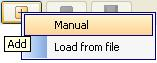
Figure 5257: Adding external schema
- Manual - The text editor on the right is editable only when Manual option is selected. The schema has to be provided manually in the text editor.
- Load from File - Opens a File Chooser to browse the required external schema.
...
To remove a schema, select the corresponding namespace and click Remove button ![]() .
.
To view a schema, select the corresponding namespace and the schema can be viewed in the text editor.
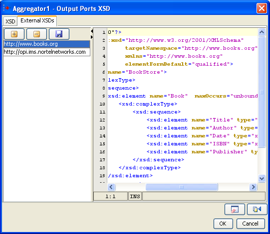
Figure 5358: Configuring external schema
...
On clicking Clear button, the schema, external schemas, root element and structure present in the schema editor will be cleared.
Fetch from Connected Source ![]()
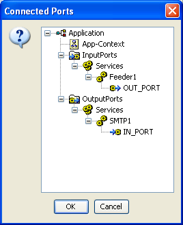
Figure 5459: List of connected ports from which schema should be fetched
...
- In Studio, navigate to Tools > Schema Repository. This opens a Schema Repository editor using which schemas can be added to schema repository.
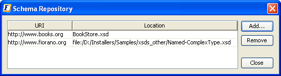
Figure 5560: Schema repository editor - Click the Add Button to add schemas to the repository, Customize Add... editor.
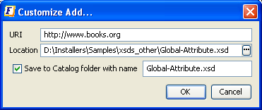
Figure 5661: Adding XSD to the schema repository - Click the ellipsis button
 to browse the required XSD.
 - Select an XSD and click OK
The values URI, Location, schema name will be automatically updated.- The URI value should not be an empty field. In case, if the schema has a target namespace, URI should be same as the target namespace of the XSD.
- The Location field displays the absolute path of the schema file.
- If the schema is to be copied and saved in the location <FIORANO_HOME>/xml-catalog/user, select the field Save to Catalog folder with name and specify a name with which the file has to be saved.
- If Save to Catalog folder with name is not selected, the file is not copied to the location <FIORANO_HOME>/xml-catalog/user and will be referred from its original location.
- Click OK to close Customize Add editor.
A new row specifying the URI and Location of the XSD will be added in the table.- To remove a schema from the schema repository, select a row from the table and click Remove.
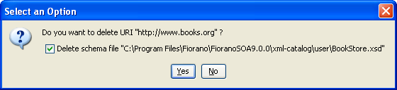
Figure 5762: Removing XSD from the schema repository - The option 'Delete schema file' specifies whether to delete the file from the system or just to remove the schema from xml-catalog. Select the check box to remove the file completely.
- In case, if the file is not copied to <FIORANO_HOME>/xml-catalog/user, the file will be deleted from its original location if this option is selected.
- To remove a schema from the schema repository, select a row from the table and click Remove.
| Anchor | ||||
|---|---|---|---|---|
|
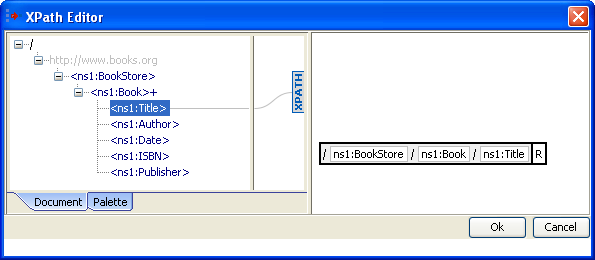
Figure 5863: XPath Editor
XPath Editor can be used for specifying path expressions to identify nodes in an XML document and for specifying conditions. The list of elements from schema provided are shown in the left panel of the editor. An XPath Editor with sample schema is shown below.
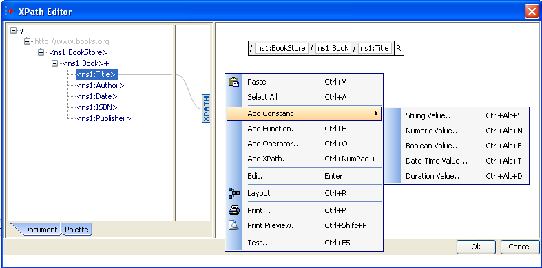
Figure 5964: Adding a constant in XPath Editor
...
A function can be added either by right clicking on the right hand side panel --> Add Function or by selecting from the list available in the palette tab which is present in the left panel as shown below.
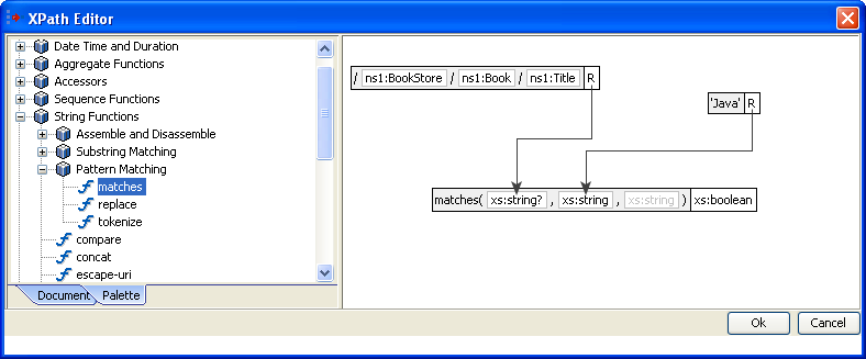
Figure 6065: XPath Editor – Palette containing different XPath functions
...
- Right-click the right panel. Select Add Constant > Boolean Value.
- Select the value as shown below.
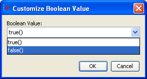
Figure 6166: Adding a boolean constant
Addition an Operator

Figure 6267: Adding an operator
- Right-click the right panel. Click the Add Operator
 button.
 - Select the operator as shown in the above figure.
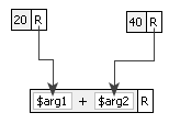
Figure 6368: Add ![]() operator
operator
The figure above illustrates a sample Xpath expression using a '+' operator. It contains two numeric constant values which are passed as arguments to the operator.
...
Named Configurations which are created earlier either from the Configuration Repository view or from the CPS itself can be re-used in other service instances.
To view all the named configurations of a particular service or resource type, use the drop-down in named configurations editor present in the CPS. A list of all configurations of similar type present in the repository is shown. Select a configuration name from the list to use that named configuration in a given service instance.
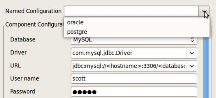
Figure 69: Load Named Configuration
After selecting the named configuration from drop down, the UI will be disabled and will not be able to edit the configuration.
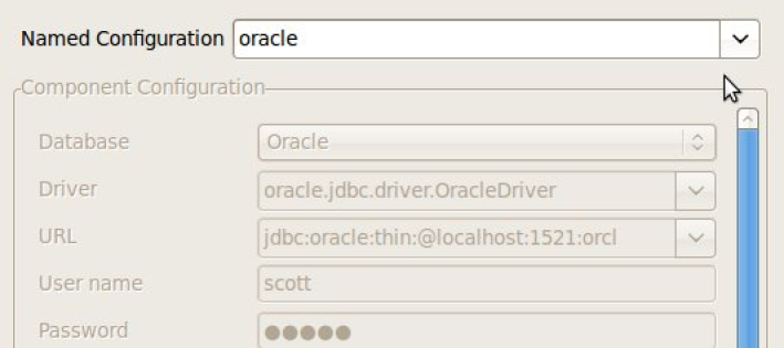
Figure 70: UI disabled after loading Named Configuration
...
Click Save and Close button or Finish button in the CPS to save the named configuration to the repository.
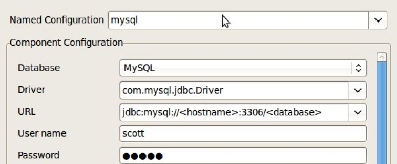
Figure 71: Save Named Configuration
...